EasyManuals Logo

Mitsubishi FX1N Series Programming Manual

Mitsubishi FX1N Series
466 pages
To Next Page IconTo Next Page
To Previous Page IconTo Previous Page
Page #435 background imageLoading...
Page #435 background image
FX Series Programmable Controllers Points Of Technique 10
10-17
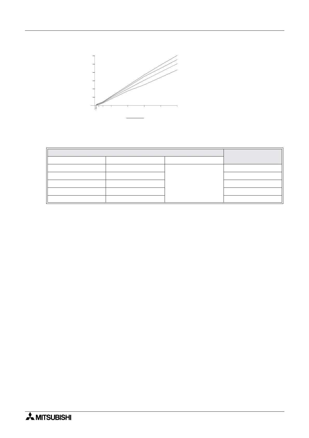
The duration of the T0, time base also affects the ripple voltage. This can be clearly seen in the
nextsetoftestdata:
The behavior of the Sink switched circuit detailed above will be similar to that of the Source
switched circuit detailed earlier.
PWM parameter setting
Measured ripple
voltage
tT
0 t/T0
100 200
0.5
1.27V
50 100 668mV
25 50 350mV
10 20 154mV
510 82mV
20 3010
52.5
1.0
40 50
t
2.0
4.0
6.0
8.0
10.0
12.0
e (volts)
L1
L2
L3
L4
Tested load impedance
(e.g. inverter impedance)
L1 - 100 k
L2 - 10 k
L3 - 4.7 k
L4 - 2.2 k

Table of Contents

Other manuals for Mitsubishi FX1N Series

Questions and Answers:

Question and Answer IconNeed help?

Do you have a question about the Mitsubishi FX1N Series and is the answer not in the manual?

Mitsubishi FX1N Series Specifications

General IconGeneral
Programming LanguageLadder Logic
Output TypeRelay, Transistor
Operating Temperature0 to 55°C
Power Supply100-240V AC or 24V DC
Program Capacity8K steps
Communication PortsRS-422
Data Memory8000 words
High-speed CountersUp to 6 channels
Expansion ModulesAvailable
Pulse Output2 points

Related product manuals