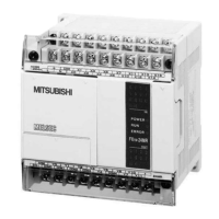
FX Series Programmable Controllers Devices in Detail 4
Chapter Contents
4. Devices in Detail....................................................................................4-1
4.1 Inputs...................................................................................................................4-1
4.2 Outputs ................................................................................................................4-2
4.3 Auxiliary Relays...................................................................................................4-3
4.3.1 General Stable State Auxiliary Relays ......................................................................4-3
4.3.2 Battery Backed/ Latched Auxiliary Relays.................................................................4-4
4.3.3 Special Diagnostic Auxiliary Relays ..........................................................................4-5
4.3.4 Special Single Operation Pulse Relays.....................................................................4-5
4.4 State Relays ........................................................................................................4-6
4.4.1 General Stable State - State Relays .........................................................................4-6
4.4.2 Battery Backed/ Latched State Relays......................................................................4-7
4.4.3 STL Step Relays .......................................................................................................4-8
4.4.4 Annunciator Flags .....................................................................................................4-9
4.5 Pointers .............................................................................................................4-10
4.6 Interrupt Pointers...............................................................................................4-11
4.6.1 Input Interrupts ........................................................................................................4-12
4.6.2 Timer Interrupts .......................................................................................................4-12
4.6.3 Disabling Individual Interrupts .................................................................................4-13
4.6.4 Counter Interrupts ...................................................................................................4-13
4.7 Constant K.........................................................................................................4-14
4.8 Constant H.........................................................................................................4-14
4.9 Timers................................................................................................................4-15
4.9.1 General timer operation...........................................................................................4-16
4.9.2 Selectable Timers....................................................................................................4-16
4.9.3 Retentive Timers .....................................................................................................4-17
4.9.4 Timers Used in Interrupt and ‘CALL’ Subroutines ...................................................4-18
4.9.5 Timer Accuracy .......................................................................................................4-18
4.10 Counters............................................................................................................4-19
4.10.1 General/ Latched 16bit UP Counters ......................................................................4-20
4.10.2 General/ Latched 32bit Bi-directional Counters.......................................................4-21
4.11 High Speed Counters ........................................................................................4-22
4.11.1 Basic High Speed Counter Operation .....................................................................4-23
4.11.2 Availability of High Speed Counters .......................................................................4-24
4.11.3 1 Phase Counters - User Start and Reset (C235 - C240) .......................................4-26
4.11.4 1 Phase Counters - Assigned Start and Reset (C246 to C250) ..............................4-27
4.11.5 2 Phase Bi-directional Counters (C246 to C250) ....................................................4-28
4.11.6 A/B Phase Counters (C252 to C255) ......................................................................4-29
4.12 Data Registers...................................................................................................4-30
4.12.1 General Use Registers ............................................................................................4-31
4.12.2 Battery Backed/ Latched Registers .........................................................................4-32
4.12.3 Special Diagnostic Registers...................................................................................4-32
4.12.4 File Registers ..........................................................................................................4-33
4.12.5 Externally Adjusted Registers .................................................................................4-34
4.13 Index Registers..................................................................................................4-35
4.13.1 Modifying a Constant...............................................................................................4-36
4.13.2 Misuse of the Modifiers ...........................................................................................4-36
4.13.3 Using Multiple Index Registers................................................................................4-36
4.14 Bits, Words, BCD and Hexadecimal..................................................................4-37
4.14.1 Bit Devices, Individual and Grouped .......................................................................4-37
4.14.2 Word Devices ..........................................................................................................4-39
4.14.3 Interpreting Word Data ............................................................................................4-39
4.14.4 Two’s Compliment...................................................................................................4-42
4.15 Floating Point And Scientific Notation ...............................................................4-43
4.15.1 Scientific Notation....................................................................................................4-44
4.15.2 Floating Point Format ..............................................................................................4-45
4.15.3 Summary Of The Scientific Notation and Floating Point Numbers..........................4-46

 Loading...


