101
FX3UC Series Programmable Controllers
User’s Manual - Hardware Edition
2 External Dimensions and Terminal Arrangement
2.2 Terminal layout
1
Outline
2
External
Dimensions
3
Generic
Specifications
4
Power Supply
Specifications
5
Input
Specifications
6
Output
Specifications
7
Examples of
Wiring for
Various Uses
8
Terminal Block
9
CC-Link/LT
Master FX
3UC
(LT only)
10
Display module
FX
3UC
(LT only)
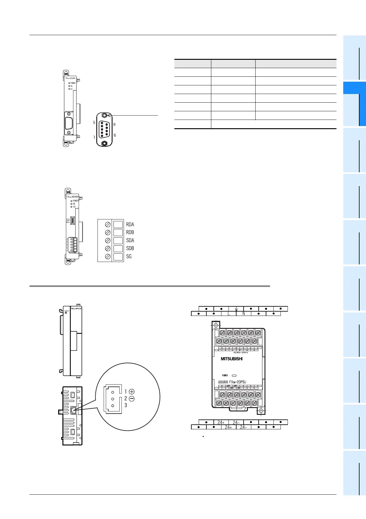
2. Communication special adapter
*1.Data terminal ready uses it as a request to send by the
handling of the control line.
*2.Data set ready uses it as a possible to send by the handling
of the control line.
2.2.7 Power supply unit
Pin No. Signal Name
1 CD(DCD) Receive carrier detection
2 RD(RXD) Receive data
3 SD(TXD) Send data
4 ER(DTR) Data terminal ready*1
5 SG(GND) Signal ground
6 DR(DSR) Data set ready*2
7, 8, 9 Not used
FX3U-232ADP(-MB)
D-SUB 9pin (male)
RS-232C connector
Screw holes: #4-40UNC
(inch screw thread)
Screws to fix
FX3U-485ADP(-MB)
*1
*1
*1. " " represents vacant terminals
(Red)
(Black)
Ground
(Green)
FX3UC-1PS-5V FX2N-20PSU
 Loading...


