EasyManua.ls Logo

Mitsubishi FX3UC Series User Manual

Mitsubishi FX3UC Series
458 pages
To Next Page IconTo Next Page
To Previous Page IconTo Previous Page
Page #370 background imageLoading...
Page #370 background image
364
FX3UC Series Programmable Controllers
User’s Manual - Hardware Edition
10 Display Module (Only FX3UC-32MT-LT)
10.21 User Message Display Function
10.21.3 Displaying a word device current value as a message
A numeric value can be displayed at the user message by combining BCD (FNC18), ASCI (FNC82), and
BMOV (FNC15) instructions.
Refer to Subsection 10.21.6 for a program example.
10.21.4 Program example 1 (user messages display switching)
The following program example is for user messages that appear in accordance with the auxiliary relay M100
to M102 ON/OFF statuses.
Note that user messages do not appear when a screen other than the "Main unit I/O operation display" is
displayed.
1. Operation
The 3 messages shown below appear in accordance with the auxiliary relay M100 to M102 ON/OFF statuses.
When auxiliary relays are ON simultaneously, the messages appear in the No.1
No.2 No.3 order.
The following is a program example in which the system information has been assigned from D50 to D90 and
from M50 to M56.
2. Character data
User message data to be displayed is created in GX Developer, and is assigned to the file registers shown
below.
Refer to Subsection 10.21.7 for character data input.
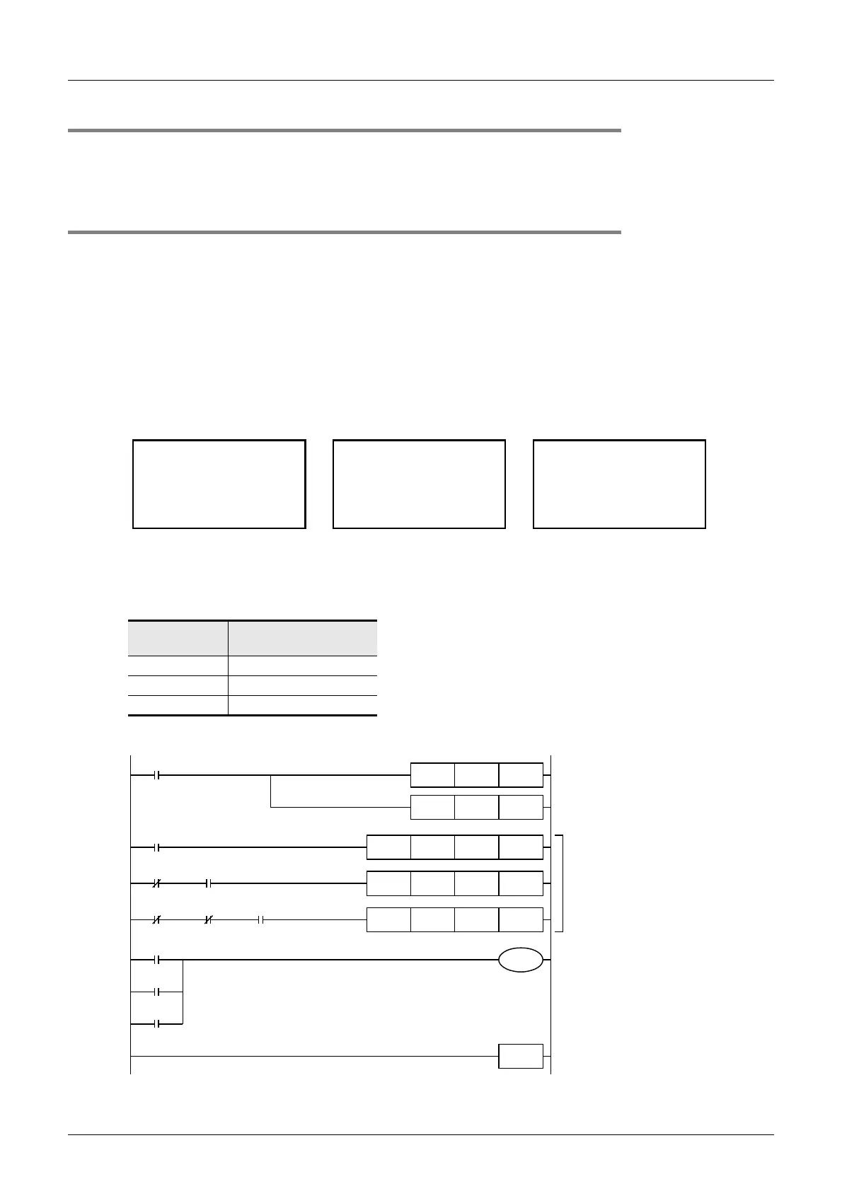
3. Program
Message No.
File Register Where
Saved
1 D1000 to D1031
2 D1032 to D1063
3 D1064 to D1095
No.1 M100 is ON
PCL
oPcessing
S
runit
Ve .2.0r
No.2 M101 is ON
<teSting
inwoNwarm
up>
upg
No.3 M102 is ON
<epOratin
05orPcss
g>
e
hirDlinlg leos
Initial puls
MOV K50 D8300
MOV K50 D8301
M8002
Sets system information (system
signal 1) at D50 to D90.
Sets system information (system
signal 2) at M50 to M56.
D1000 D59 K32
Sets character data at D59 to D90,
depending on conditions.
BMOV
M100
D1032 D59 K32BMOV
M101M100
D1064 D59 K32BMOV
M102M100 M101
Displays character data saved at D59
to D90.
M100
M54
M101
M102
END
Message No.1 display
Message No.2 display
Message No.3 display

Table of Contents

Other manuals for Mitsubishi FX3UC Series

Question and Answer IconNeed help?

Do you have a question about the Mitsubishi FX3UC Series and is the answer not in the manual?

Mitsubishi FX3UC Series Specifications

General IconGeneral
BrandMitsubishi
ModelFX3UC Series
CategoryController
LanguageEnglish

Summary

Safety Precaution

INSTALLATION PRECAUTIONS

Covers power cutoff, environmental use, secure installation, flat surfaces, expansion boards, debris, dust sheets, and cable connections.

Outline

Major Features

Details basic functions, extension units, program memory, instruction types, built-in switches, RUN writing, clock function, programming tools, and remote debugging.

List of Products

Provides a comprehensive list of products, including main units, I/O extension blocks, special function blocks, adapters, and terminal blocks.

Connection to programming tool

Details how to connect a programming tool to the PLC, including peripheral devices and expansion boards.

System overall configuration

Classifies connectable products into groups and provides examples of system configuration with extension units and CC-Link/LT.

Rules of System Configuration

Outlines requirements for system configuration, including input/output points, 5V DC power supply capacity, and number of units per group.

Number of Input/Output Points and Maximum Number of Input/Output Points

Details the number of I/O points and maximum limits based on PLC version, network type, and system configuration.

Calculation of 5V DC power supply capacity (current consumption)

Explains how to calculate the required 5V DC power supply capacity for extension equipment and the main unit.

Restriction in number of units in each group

Lists the limitations on the number of expansion boards, special adapters, and special function units/blocks that can be connected.

Number of occupied I/O points and 5V DC current consumption

Shows the number of occupied I/O points and 5V DC current consumption for various main units, special adapters, expansion boards, and I/O extension devices.

Assignment of Input/Output Numbers (X/Y)

Explains rules for assigning input/output numbers (X/Y) to remote I/O units and extension blocks, including automatic assignment.

Generic Specifications/Installation Work

Generic Specifications

Details environmental specifications like ambient temperature, humidity, vibration resistance, shock resistance, noise, voltage, grounding, and working atmosphere.

Procedures for Installing on and Detaching from DIN Rail

Explains the step-by-step process for mounting and removing units from a DIN rail, including specific procedures for different series.

Connection of power supply cable

Details power cable types, connection procedures for main units and extension blocks, and power supply considerations for FX3UC series.

Connection between main unit and extension equipment

Explains various methods for connecting extension equipment to the main unit, including methods A, B, C, and D.

Power Supply Specifications and External wiring

Selection of the external DC power supply to prepare

Explains power supply input specifications for main units and extension power supply units, including fuse and rush current.

Example External Wiring

Illustrates wiring for systems with two or more external DC power supplies, emphasizing correct minus line connection.

Input Specifications and External wiring

Sink and source input (24V DC input type)

Explains sink input and source input concepts, providing examples and instructions for using them.

24V DC Input Type

Covers 24V DC input specifications, including input circuit diagrams, signal voltage, impedance, current, sensitivity, response time, and insulation.

Input Interruption (I00 to I50) - With Delay Function

Details input interruption function, delay function, and non-overlap of input numbers for points X000 to X007.

Pulse Catch (M8170 to M8177)

Describes the pulse catch function, its 8 input points, allocation of special memories, and non-overlap of input numbers.

High-speed Counters (C235 to C255)

Lists the device numbers, classification, and input allocation for high-speed counters.

Output Specification and External Wiring

Sink and Source Output (Transistor)

Classifies transistor outputs into sink and source types, explaining their circuit differences and providing examples.

Transistor Output

Details output specifications for transistor outputs, including number of points, connecting type, output form, external power supply, and max load.

Relay Output [FX2NC/FX0N/FX2N Extension Blocks]

Provides specifications for relay output, including output terminals, external power supply, max load, minimum load, leakage current, response time, and circuit insulation.

Triac (SSR) Output [FX2N-16EYS]

Details specifications for Triac (SSR) output, including output terminals, external power supply, max load, minimum load, leakage current, response time, and circuit insulation.

Examples of Wiring for Various Uses

Input Interruption - With Delay Function, Pulse Catch

Shows wiring examples for input interruption and pulse catch using inputs X000 to X005, including precautions.

Digital Switch [DSW (FNC 72)/BIN (FNC 19)]

Shows wiring examples for capturing values from a 2-digit digital switch using BIN instructions, for both sink and source wiring.

Ten Key Input [TKY (FNC 70)]

Gives examples of wiring for capturing values from a ten-key pad to D100 using TKY instructions, for sink and source wiring.

Hexadecimal Input [HKY (FNC 71)]

Provides examples of wiring for capturing hexadecimal values from 16 switches to D100 and M0 to M5 using HKY instructions.

Input Matrix [MTR (FNC 52)]

Illustrates wiring examples for input extension block + output extension block using MTR instructions for sink and source wiring.

CC-Link/LT Built-in master ability (Only FX3UC-32MT-LT)

DESIGN PRECAUTIONS

Advises on cable routing, secure installation, and avoiding excessive force on connectors.

WIRING PRECAUTIONS

Warns against touching live terminals, advises power cutoff for cleaning, and cautions regarding battery handling.

Outline

Explains the CC-Link/LT master function, network advantages like high-speed refresh, dedicated connectors, and built-in power supply.

Outline of System

Details CC-Link/LT system overview, including network capabilities, cable options, device assignment, and power supply.

CC-Link/LT specifications

Provides performance specifications for CC-Link/LT, including connectable stations, point modes, link scan times, and network topology.

Performance specifications

Lists performance specs like number of connectable stations, point modes, link scan times, communication speed, protocol, network topology, and error control.

Network wiring specifications

Details network wiring specifications for CC-Link/LT, including communication speed, distance between stations, and number of modules per drop line.

Cable specifications

Lists specifications for CC-Link/LT dedicated flat cables, VCTF cables, and high flexible cables, including type, voltage, number of cores, and resistance.

System configuration [CC-Link/LT Built-in master ability]

Shows system configuration examples and cautions for CC-Link/LT, including connection cables, connectors, and terminating resistors.

CC-Link/LT total configuration

Describes the total system configuration for CC-Link/LT, including connection methods and cautions.

Selection of the power supply for CC-Link/LT

Outlines the system power calculation procedure, including current consumption, voltage drop, and minimum operating voltage checks.

System power calculation procedure

Details the steps to calculate system power, including current consumption, voltage drop, and checking against minimum operating voltage.

System power calculation procedure (FX3UC-32MT-LT built-in power supply)

Provides calculation methods for current consumption and voltage drop using simplified graphs and formulas for the built-in power supply.

Selection based on the calculation formula (at supply voltage: 24V DC, ambient temperature: 20°C)

Explains calculation formulas for voltage drop using dedicated flat cables, VCTF cables, and high flexible cables.

Connection of Cables, Connectors and Terminating Resistors

Guides on connecting CC-Link/LT cables, selecting connectors, and attaching terminating resistors according to procedures.

Procedure

Outlines the steps for connecting cables, connectors, and terminating resistors, including turning power OFF and attaching connectors.

Inserting a connector [to power supply adapter/dedicated power supply]

Details how to connect the built-in master to power supply adapters or dedicated power supplies using LINK and LINK/POWER connectors.

Connecting a connection cable to the CC-Link/LT interface connector

Explains how to connect a connection cable to the CC-Link/LT interface connector on the master.

How to attach a terminating resistor

Guides on attaching terminating resistors to the FX3UC-32MT-LT built-in master and trunk line sides.

Setting of CC-Link/LT built-in master and remote I/O units

Explains how to set DIP switches for built-in master operation and station numbers for remote I/O stations.

Setting DIP switches in built-in master (operation mode/Communication speed/ Point mode)

Details how to set DIP switches for operation mode, communication speed, and point mode on the built-in master.

Details of the operation mode

Explains the three operation modes (ONLINE, CONFIG, TEST) and how to set them using DIP switches and check status LEDs.

Setting of an Operation mode and on DIP switch

Shows how to set the operation mode (ONLINE, CONFIG, TEST) using DIP switches and provides setting examples.

CONFIG mode

Provides cautions regarding editing detailed remote station information and the ERR LED behavior in CONFIG mode.

TEST mode (self-loop-back test)

Details the procedure for executing the TEST mode (self-loop-back test) and interpreting status indicator LEDs.

Display Module (Only FX3UC-32MT-LT)

Test Operation, Adjustment, Maintenance and Troubleshooting

STARTUP AND MAINTENANCE PRECAUTIONS

Covers precautions for attaching/detaching memory cassettes, PLC modification, connecting/disconnecting cables, and devices.

Performance Specifications

Operation of Special Devices (M8000 -, D8000 -)

Instruction List

Related product manuals