275
FX3UC Series Programmable Controllers
User’s Manual - Hardware Edition
9 CC-Link/LT Built-in master ability (Only FX3UC-32MT-LT)
9.8 Connection of Cables, Connectors and Terminating Resistors
1
Outline
2
External
Dimensions
3
Generic
Specifications
4
Power Supply
Specifications
5
Input
Specifications
6
Output
Specifications
7
Examples of
Wiring for
Various Uses
8
Terminal Block
9
CC-Link/LT
Master FX
3UC
(LT only)
10
Display module
FX
3UC
(LT only)
9.8.4 How to attach connectors for the VCTF cable/high flexible cable (terminal/T-branch
processing)
This section explains how to attach VCTF cable connectors and high flexible cable connectors.
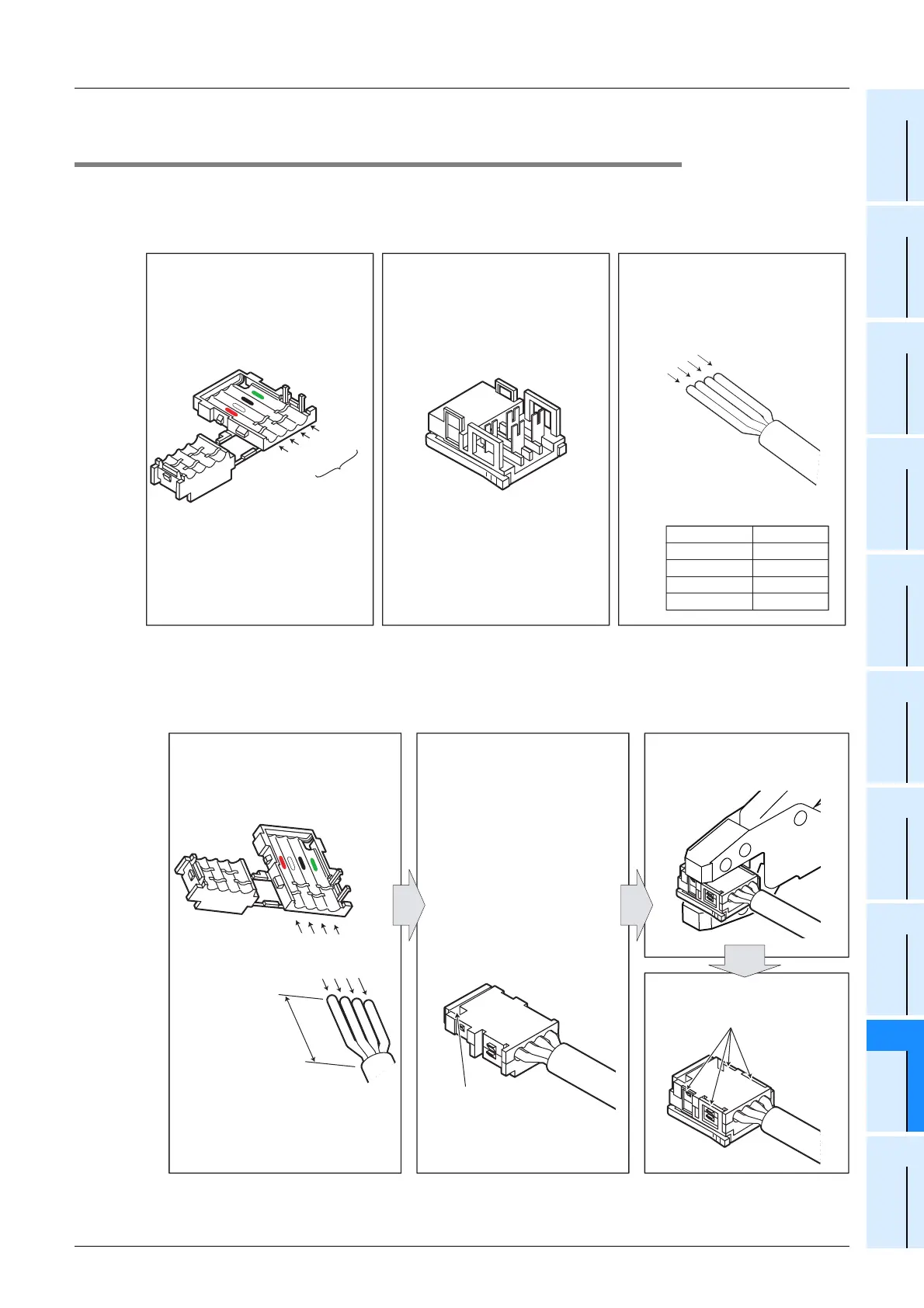
1. Components
The components are shown below.
2. Attachment procedure
The procedure is shown below.
1) Terminal processing procedure
Applicable attachment: Terminal resistor attachment at the trunk line end and terminal processing
Component 1 : Cover Component 2 : Body (Aqua) Component 3 : VCTF cable/
Relationship between wire
color and signal
Signal name Wire color
Red+24V
DA
DB
24G
White
Black
Green
High flexible cable
VCTF cable connector : Green
Green
Black
White
Red
Cover
inside
Green
Black
White
Red
Flexible cable connector : Yellow green
Green
Black
White
Red
high flexible cable with the same
Correctly align the VCTF cable/1)
colored sections.
the VCTF cable/high flexible
Close the cover to firmly hold2)
cover, and press-fit them
with pliers, etc.
Combine the body with the3)
engaged in four positions.
Now, press-fitting is finished.
Confirm that the latch is4)
cable in place.
When the cable is correctly
wired, the green wire can be
seen from the notched window.
If the red, white or black wire is
seen from the notched window,
the wiring is wrong.
Open the cover, and correctly
set the cable.
Incorrect wiring causes failures
in the unit.
Green : Correct wiring
Red, white or black : Incorrect
wiring
40mm
(1.57")
 Loading...


