257
FX3UC Series Programmable Controllers
User’s Manual - Hardware Edition
9 CC-Link/LT Built-in master ability (Only FX3UC-32MT-LT)
9.4 Selection of connection cables, connectors and terminal resistors
1
Outline
2
External
Dimensions
3
Generic
Specifications
4
Power Supply
Specifications
5
Input
Specifications
6
Output
Specifications
7
Examples of
Wiring for
Various Uses
8
Terminal Block
9
CC-Link/LT
Master FX
3UC
(LT only)
10
Display module
FX
3UC
(LT only)
9.3.3 Cautions on use
1. About equipment for CC-Link
Equipment for CC-Link cannot be connected to the CC-Link/LT system.
2. About installation
For the installation conditions of the power adapter (dedicated power supply) and remote
module, refer to the appropriate instruction manual. Install each of them correctly.
9.4 Selection of connection cables, connectors and terminal resistors
For the latest information on the connection cables, connectors and terminal resistors, refer to the homepage
of the CC-Link Association or catalogs (issued by the CC-Link Association).
→ The homepage of the CC-Link Association (http://www.cc-link.org/)
9.4.1 Selection of cables
→ For details on terminal resistors, refer to the homepage of
the CC-Link Association or CC-Link/ LT catalogs.
9.4.2 Selection of connectors
The table below shows the specifications of the VCTF cable connector and high flexible cable connector.
→ For details on terminal resistors, refer to the homepage of
the CC-Link Association or CC-Link/ LT catalogs.
*1. The color of the body is light-blue
9.4.3 Selection of terminal resistors
Use the CL9-TERM (gray). When only dedicated flat cables are used in the system, the CL9-RYVK (black) is also
available.
Make sure to use terminal resistors that have the same model name on both ends of the trunk line.
→ For details on terminal resistors, refer to the homepage of
the CC-Link Association or CC-Link/ LT catalogs.
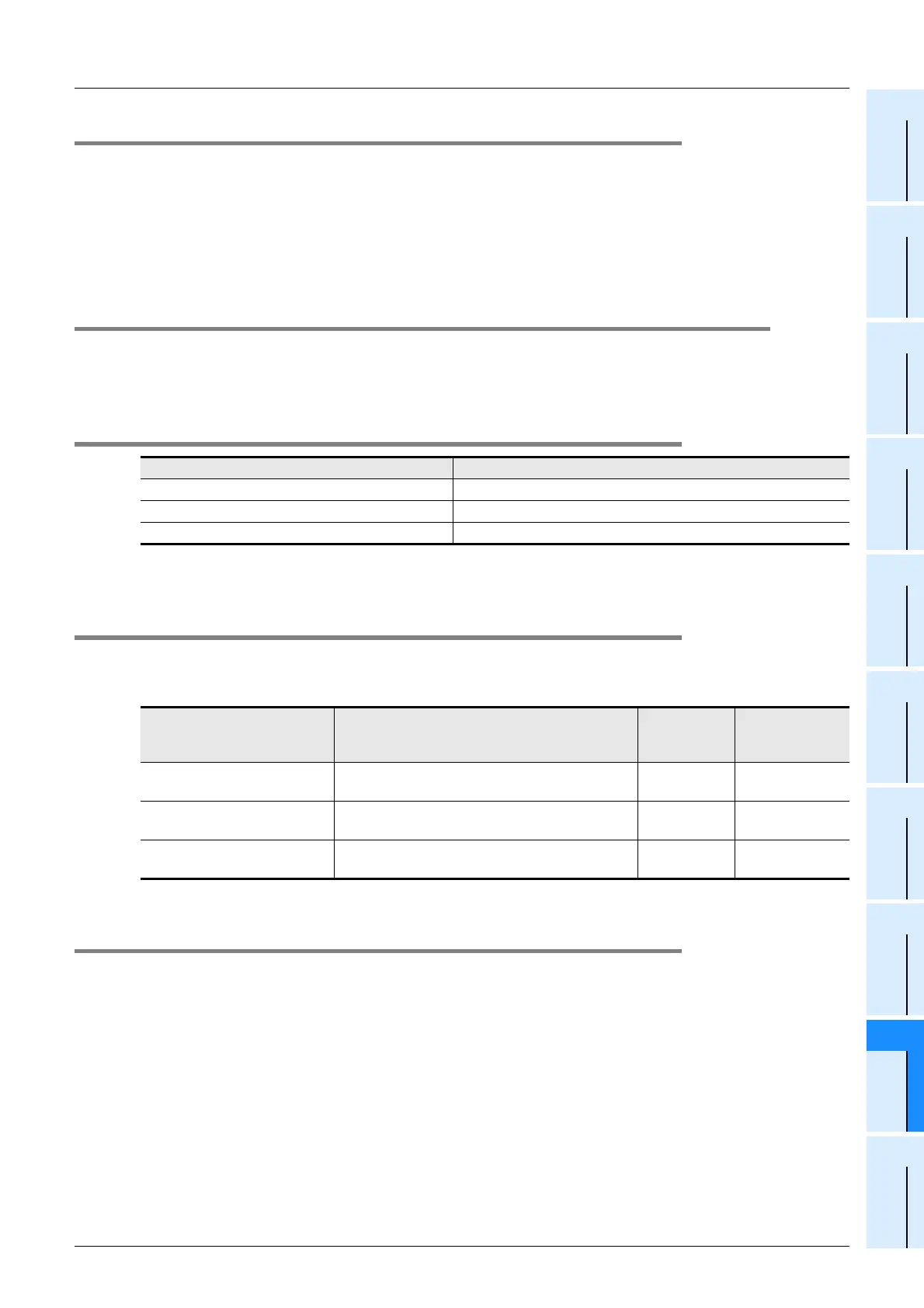
Connection cable Reference
CC-Link/LT dedicated flat cable For specifications, refer to Subsection 9.2.3.
VCTF cable For specifications, refer to Subsection 9.2.3.
High flexible cable For specifications, refer to Subsection 9.2.3.
Connector Model name (manufacturer name)
Cover color
*1
Cable insulator
outside
diameter
Dedicated flat cable connector
CL-9-CNF-18
(Mitsubishi Electric System & Service Co.Ltd)
Light blue -
VCTF Cable Connector
CL9-CNR-23
(Mitsubishi Electric System & Service Co.Ltd)
Green
ø 2.1 to 2.4
High Flexible Cable Connector
CL9-CNR-20
(Mitsubishi Electric System & Service Co.Ltd)
Yellowish
green
ø 1.8 to 2.1
 Loading...


