273
FX3UC Series Programmable Controllers
User’s Manual - Hardware Edition
9 CC-Link/LT Built-in master ability (Only FX3UC-32MT-LT)
9.8 Connection of Cables, Connectors and Terminating Resistors
1
Outline
2
External
Dimensions
3
Generic
Specifications
4
Power Supply
Specifications
5
Input
Specifications
6
Output
Specifications
7
Examples of
Wiring for
Various Uses
8
Terminal Block
9
CC-Link/LT
Master FX
3UC
(LT only)
10
Display module
FX
3UC
(LT only)
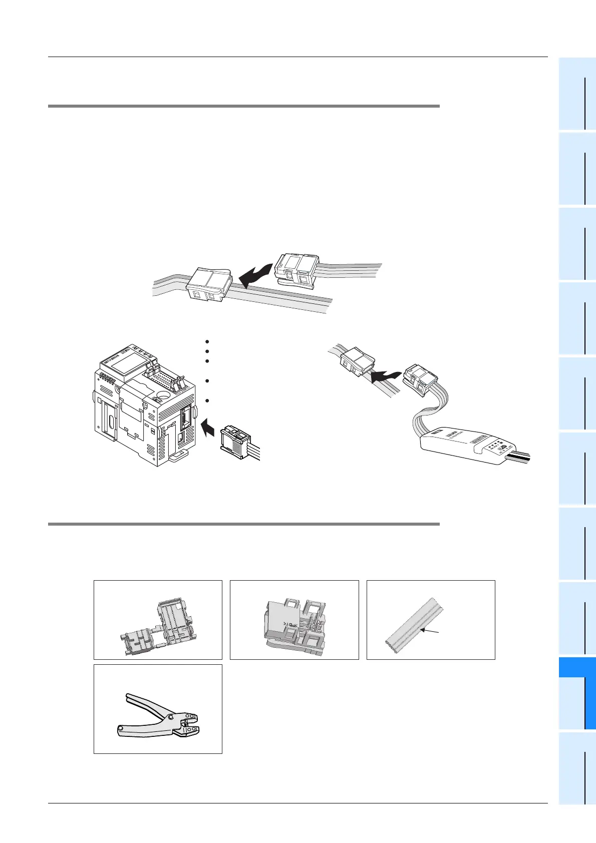
9.8.2 Connection outline for connection cables (Example: CC-Link/LT dedicated flat
cables)
This subsection explains how to connect CC-Link/LT dedicated flat cables.
1) The connection cable connection order has no relevance to the station number.
2) Make sure to place the CC-Link/LT built-in master on one end of the trunk line.
Connect a terminating resistor for the CC-Link/LT built-in master within 20cm from a connector.
3) Make sure to connect a terminating resistor on each end of the CC-Link/LT trunk line.
Connection example for the CC-Link/LT dedicated flat cable
Connect the dedicated flat cable to a T branch or remote I/O unit using dedicated flat cable connectors.
9.8.3 How to attach connectors for the dedicated flat cable (terminal/T-branch
processing)
This paragraph explains how to attach connectors for the dedicated flat cable.
1. Components
The components are as shown below.
T-branch area
Connection area (built-in master, remote station, power supply)
Connector for dedicated
flat cable
Connector for dedicated
flat cable
Connector for dedicated
flat cable
Connector for dedicated
flat cable
Connector for dedicated
flat cable
Cable type remote
I/O module
Built-in master
Power adapter
Terminal block type
remote module
Sensor connector type
remote module
MIL connector type remote
I/O module
Component 1 : Cover
L-TOON-N
Pressure-welding tool
for the communication connector
Component 2 : Body
Orange
Component 3 : Dedicated flat cable
 Loading...


