267
FX3UC Series Programmable Controllers
User’s Manual - Hardware Edition
9 CC-Link/LT Built-in master ability (Only FX3UC-32MT-LT)
9.6 Selection of the power supply for CC-Link/LT
1
Outline
2
External
Dimensions
3
Generic
Specifications
4
Power Supply
Specifications
5
Input
Specifications
6
Output
Specifications
7
Examples of
Wiring for
Various Uses
8
Terminal Block
9
CC-Link/LT
Master FX
3UC
(LT only)
10
Display module
FX
3UC
(LT only)
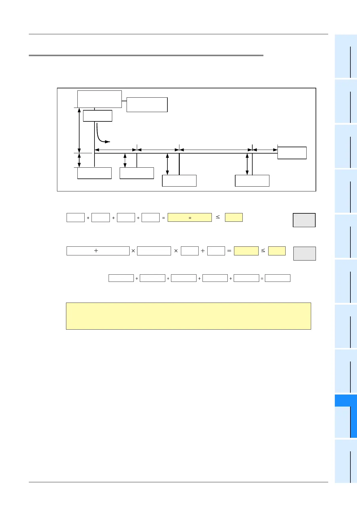
9.6.4 System configuration example 1
In this system configuration example using only dedicated flat cables, both the current consumption and the
voltage drop are small.
System configuration example
1) Current consumption calculation
Total current consumption
2) Voltage drop calculation
3) Confirmation related to the minimum operating voltage (20.4V DC) of the module
24V - 2.612V = 21.388V
≥ 20.4V
Station a)
100mA
Station d)
60mA
Terminating
resistor
5m
2m
4m
4m
5m 0.5m
- The current consumption of each station shall include the
current consumption of the connected I/O equipment.
- It is supposed that the general-purpose power supply
satisfies the required condition.
Terminating
resistor
5m 10m
Power supply
FX
3
UC
-32MT-LT
(Built-in master+
Built-in power supply)
Station c)
80mA
General-purpose
power supply
24V DC
2m
Station b)
60mA
station station station station
a) b) c) d)
60mA80mA
60mA100mA
300mA 0.30A 0.35A
OK!!
(29m (95’1") Constant : 55) Constant : 0.06 0.3A 1.1V 2.612V 3.6V
5m (16’4") 4m (13’1") 29m (95’1")
Maximum distance : From the main unit to the farthest station, station d)
10m (32’9")5m (16’4")5m (16’4")
OK!!
From 1), 2) and 3) above, the system can be configured using only the built-in
power supply with regard to both the current and voltage restrictions.
 Loading...


