384
FX3UC Series Programmable Controllers
User’s Manual - Hardware Edition
12 Test Operation, Adjustment, Maintenance and Troubleshooting
12.1 Preparation for Test Operation
12.1 Preparation for Test Operation
12.1.1 Preliminary inspection [power OFF]
Incorrect connection of the power supply terminal, contact of the DC input wire and power supply wire, or
short-circuiting of output wires may result in serious damage.
Before applying power, check that the power supply and ground terminals are connected correctly and input/
output devices are wired properly.
12.1.2 Connection to built-in programming connector [power ON, PLC STOP]
1 Turn on the PLC power.
Make sure that the RUN/STOP switch of the PLC is set to STOP, and turn the power on.
2 Check the program.
Check for circuit errors and grammatical errors with the program check function of the program-
ming tool.
3 Transfer the sequence program.
Write the program to the memory cassette with the programming tool.
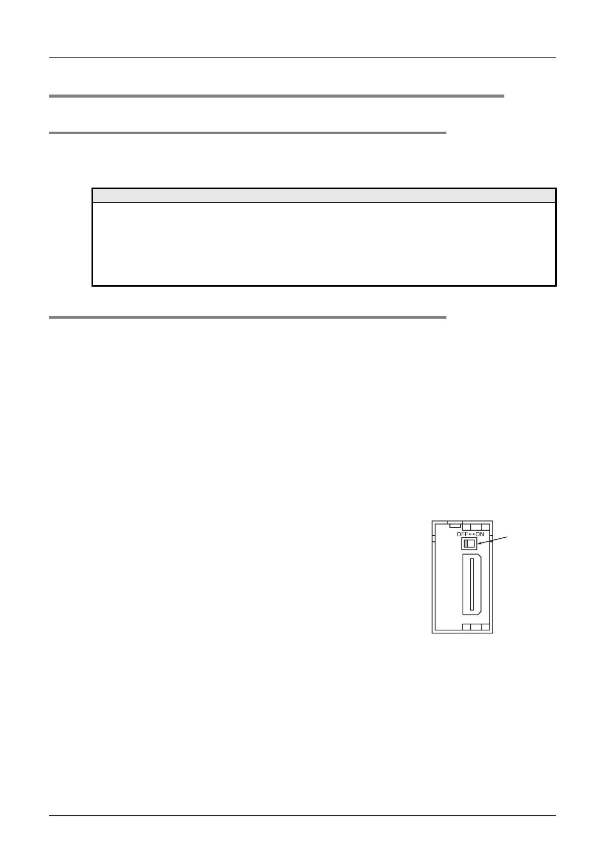
When the memory cassette is used
Make sure to set the PROTECT switch of the memory cassette to
OFF (shown right).
→ For details on handling of the memory cassette,
refer to Section 11.1.
4 Verify the sequence program.
Verify that the program has been correctly written to the memory cassette.
5 Execute PLC diagnosis.
Check for errors in the PLC main body with the PLC diagnostic function of the programming tool.
→ For details on the PLC diagnosis with the display module or GX Developer, refer to Section 12.6.
Notes
The dielectric withstand voltage and insulation resistance test of the PLC should be measured in accordance with the
following procedures.
1) Remove all input/output wires and power supply wires from the PLC.
2) Connect all terminals except the grounding terminal with a crossover wire in the PLC single unit.
3) Measure the voltage between the crossover wire and the grounding terminal.
Dielectric withstand voltage: 500V AC for 1min
Insulation resistance: 500V DC/5MΩ or more
PROTECT
switch
 Loading...


