107
FX3UC Series Programmable Controllers
User’s Manual - Hardware Edition
3 Generic Specifications/Installation Work
3.3 Procedures for Installing on and Detaching from DIN Rail
1
Outline
2
External
Dimensions
3
Generic
Specifications
4
Power Supply
Specifications
5
Input
Specifications
6
Output
Specifications
7
Examples of
Wiring for
Various Uses
8
Terminal Block
9
CC-Link/LT
Master FX
3UC
-LT only
10
Display module
FX
3UC
-LT only
1
Outline
2
External
Dimensions
3
Generic
Specifications
4
Power Supply
Specifications
5
Input
Specifications
6
Output
Specifications
7
Examples of
Wiring for
Various Uses
8
Terminal Block
9
CC-Link/LT
Master FX
3UC
(LT only)
10
Display module
FX
3UC
(LT only)
3.3 Procedures for Installing on and Detaching from DIN Rail
The main unit, FX2NC I/O extension block, FX2NC/FX3UC special function block, and FX3U special adapter
can be installed on a DIN46277 rail [35mm (1.38") wide]. (It cannot be installed directly with screws.)
The FX
0N/FX2N I/O extension block, FX0N/FX2N/FX3U special function block, and FX3U special adapter can
be installed on a DIN46277 rail [35mm (1.38") wide] and directly mounted.
→ For the installation of remote I/O stations, dedicated power supply and power supply adapter for
CC-Link/LT, refer to the manual of each product.
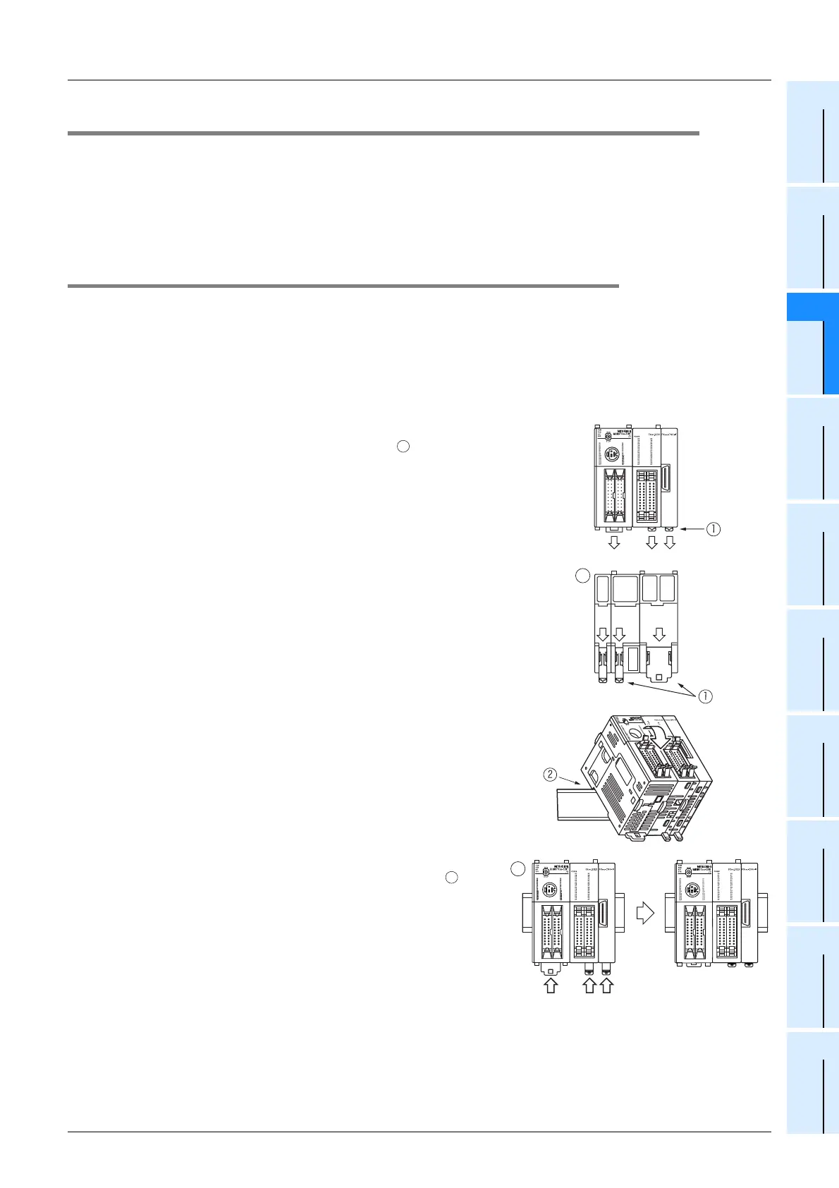
3.3.1 Procedures for installing to and removing from DIN rail
1. FX3UC Series main unit, FX2NC Series I/O extension block, FX2NC/FX3UC Series special
function block, Extension power supply unit, FX
2NC-CNV-IF
(Example : FX3UC-32MT/D)
1) Connect all of the main unit, I/O extension blocks for FX
2NC, special extension blocks for FX2NC/FX3UC,
extension power supply unit and FX
2NC-CNV-IF.
→ For connecting method, refer to Subsection 3.4.2.
2)
Push the DIN rail mounting hooks
c
of all connected units/
blocks as shown in the fi
gure on the right .
3) Align the upper side of the DIN rail mounting groove with the
DIN rail (
d
in the figure on the right).
4) While pressing the main unit onto the DIN rail, lock the DIN
rail mounting hooks as shown in the figure below .
A
A
B
B
 Loading...


