103
FX3UC Series Programmable Controllers
User’s Manual - Hardware Edition
3 Generic Specifications/Installation Work
1
Outline
2
External
Dimensions
3
Generic
Specifications
4
Power Supply
Specifications
5
Input
Specifications
6
Output
Specifications
7
Examples of
Wiring for
Various Uses
8
Terminal Block
9
CC-Link/LT
Master FX
3UC
-LT only
10
Display module
FX
3UC
-LT only
1
Outline
2
External
Dimensions
3
Generic
Specifications
4
Power Supply
Specifications
5
Input
Specifications
6
Output
Specifications
7
Examples of
Wiring for
Various Uses
8
Terminal Block
9
CC-Link/LT
Master FX
3UC
(LT only)
10
Display module
FX
3UC
(LT only)
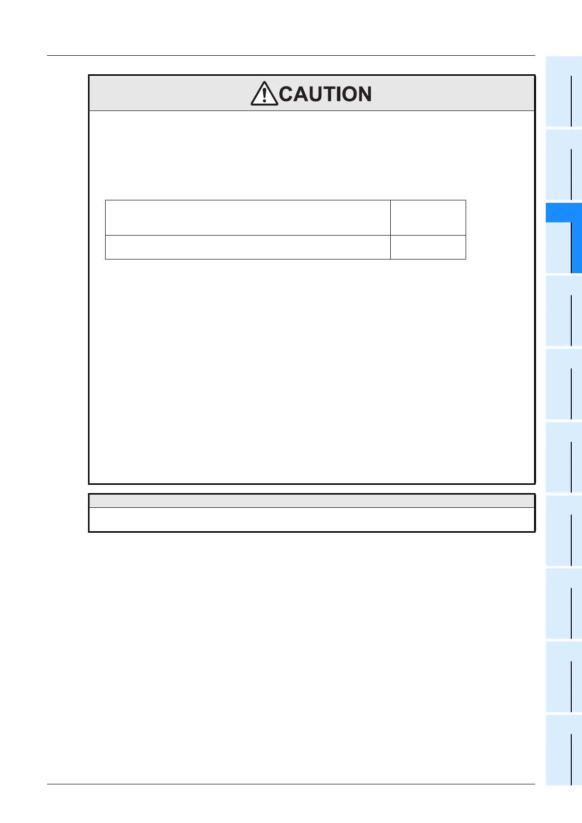
INSTALLATION PRECAUTIONS
• Use the product within the generic environment specifications described in Section 3.1 of this manual.
Never use the product in areas with excessive dust, oily smoke, conductive dusts, corrosive gas (salt air, Cl
2, H2S,
SO
2 or NO2), flammable gas, vibration or impacts, or exposed to high temperature, condensation, or rain and
wind.
If the product is used in such conditions, electric shock, fire, malfunctions, deterioration or damage may occur.
• Do not touch the conductive parts of the product directly.
Doing so may cause device failures or malfunctions.
• Install the product securely using a DIN rail or mounting screws.
• Install the product on a flat surface.
If the mounting surface is rough, undue force will be applied to the PC board, thereby causing nonconformities.
• Make sure to affix the expansion board with tapping screws.
Tightening torque: 0.3 to 0.6 N
•
m
Loose connections may cause malfunctions.
• When drilling screw holes or wiring, make sure that cutting and wiring debris do not enter the ventilation slits.
Failure to do so may cause fire, equipment failures or malfunctions
• Be sure to remove the dust proof sheet from the PLC's ventilation port when installation work is completed.
Failure to do so may cause fire, equipment failures or malfunctions
• Connect the extension cables, peripheral device cables, input/output cables and battery connecting cable
securely to their designated connectors.
Loose connections may cause malfunctions.
• Connect the display module, memory cassette, FX
2NC Series I/O extension blocks, FX2NC-CNV-IF, extension
power supply unit and expansion board securely to their designated connectors.
Loose connections may cause malfunctions.
• Turn off the power before attaching or detaching the following devices.
Failure to do so may cause device failures or malfunctions.
- Peripheral devices, display module, expansion boards and special adapters
- Extension blocks, FX Series terminal blocks, Connector conversion adapter and extension power supply unit
- Battery and memory cassette
Note
• When a dust proof sheet is supplied with an extension unit/ block, keep the sheet applied to the ventilation slits
during installation and wiring work.
Main unit, FX2NC Series I/O extension blocks, FX2NC/FX3UC Series
special function blocks, special adapter, extension power supply unit,
FX
2NC-CNV-IF, FX2N-10GM, FX2N-20GM, FX Series terminal blocks
DIN rail only
FX
0N/FX2N Series I/O extension blocks, FX0N/FX2N/FX3U Series special
function blocks, FX
2N-1RM(-E)
DIN rail or direct
mounting
 Loading...


