120
FX3UC Series Programmable Controllers
User’s Manual - Hardware Edition
3 Generic Specifications/Installation Work
3.10 Connection of power supply cable
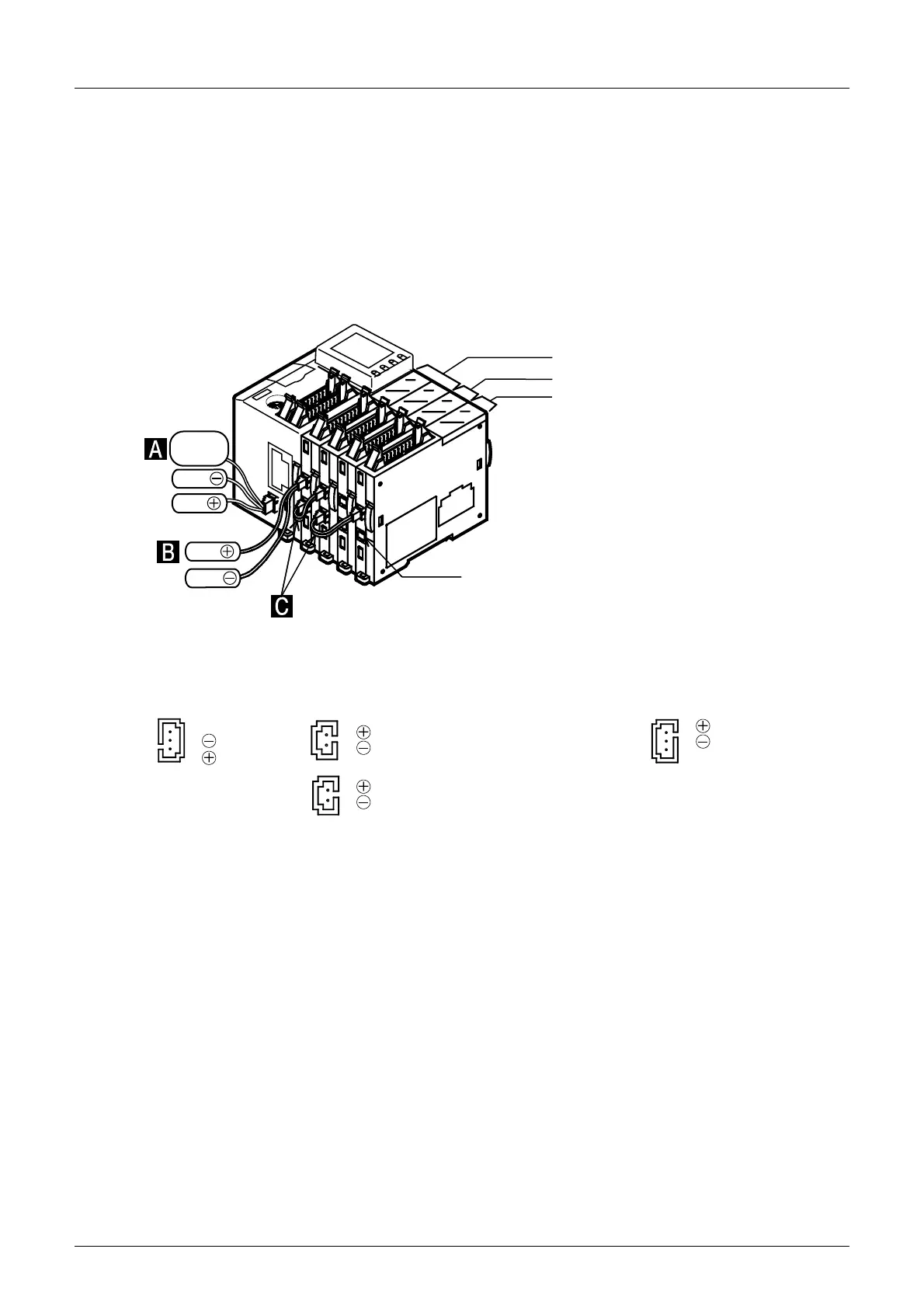
• Wiring from the FX2NC-EX, FX2NC-16EX-T or FX2NC/FX3UC Series special extension block to
another block.
Two power connectors of the FX
2NC-EX, FX2NC-16EX-T and FX2NC/FX3UC Series special extension
blocks are connected in parallel inside the block, and there is no distinction between the power inlet side
and the power outlet side. Either connector can be used for wiring. At shipment from the factory, a resin
cover is attached to the lower connector. Use the upper connector first. Remove the resin cover from the
lower connector only when performing crossover wiring for another block.
(The FX
2NC-EX-DS and FX2NC-16EX-T-DS do not have a power connector, and receive power from
the input connector. It is not necessary to remove the resin cover.)
2. FX3UC-32MT-LT
• Wiring from the FX2NC-EX, FX2NC-16EX-T or FX2NC/FX3UC Series special function block to another
block.
Two power connectors of the FX
2NC-EX, FX2NC-16EX-T or FX2NC/FX3UC Series special function
blocks are connected in parallel inside the block, and there is no distinction between the power inlet side
and the power outlet side. Either connector can be used for wiring.
At shipment from the factory, a resin cover is attached to the lower connector. Use the upper connector
first. Remove the resin cover from the lower connector only when performing crossover wiring for another
block.
Black
Green
Ground
FX
3UC-32MT-LT FX3UC-1PS-5V
FX
3UC-32MT-LT
Output extension block
Input extension block
Input extension block
Resin cover
Red
Black
Red
Crossover wiring
between the input
extension block.
At shipment from the factory, a resin cover is attached
to the lower connector.
Connect the upper connector first.
Remove the resin cover from the lower connector
when performing crossover wiring for the later block.
The figure below shows the pin numbers of the power connectors.
Extension block
2 (Black)
1 (Red)
3 Ground(Green)
2 (Black)
1 (Red)
2 (Black)
1 (Red)
At shipment from the factory, a
resin cover is attached to the
lower connector.
2 (Black)
1 (Red)
3 Ground(Green)
 Loading...


