129
FX3UC Series Programmable Controllers
User’s Manual - Hardware Edition
4 Power Supply Specifications and External wiring
1
Outline
2
External
Dimensions
3
Generic
Specifications
4
Power Supply
Specifications
5
Input
Specifications
6
Output
Specifications
7
Examples of
Wiring for
Various Uses
8
Terminal Block
9
CC-Link/LT
Master FX
3UC
(LT only)
10
Display module
FX
3UC
(LT only)
WIRING PRECAUTIONS
• Do not touch any terminal while the PLC's power is on.
Doing so may cause electric shock or malfunctions.
• Before cleaning or retightening terminals cut off all phases of the power supply externally.
Failure to do so may cause electric shock.
• Make sure to connect the battery for memory backup correctly.
Do not charge, disassemble, heat, short-circuit, or expose the battery to fire.
Doing so may rupture or ignite it.
• Before modifying or disrupting the program in operation or running the PLC, carefully read through this manual
and the associated manuals and ensure the safety of the operation.
An operation error may damage the machinery or cause accidents.
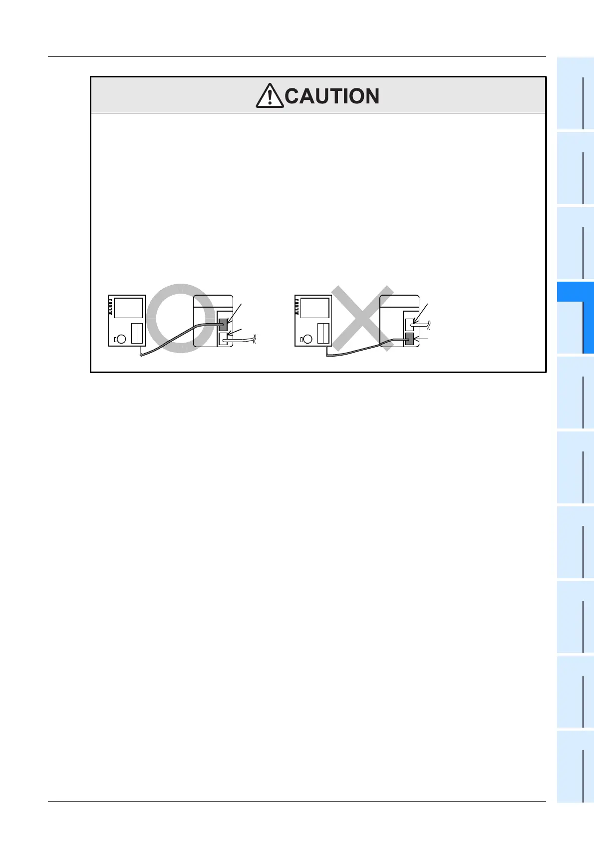
•The FX
3UC-32MT-LT has a built-in power supply. When connecting the power supply adapter or dedicated power
supply for CC-Link/LT, connect the built-in master to the LINK connector in the power supply adapter or dedicated
power supply.
Connection to the LINK/POWER connector may cause failures.
Correct
connection
LINK
connector
LINK/
POWER
connector
Wrong
connection
LINK
connector
LINK/
POWER
connector
Power adapter or Dedicated
Power Supply
Power adapter or Dedicated
Power Supply
 Loading...


