133
FX3UC Series Programmable Controllers
User’s Manual - Hardware Edition
4 Power Supply Specifications and External wiring
4.2 Example External Wiring
1
Outline
2
External
Dimensions
3
Generic
Specifications
4
Power Supply
Specifications
5
Input
Specifications
6
Output
Specifications
7
Examples of
Wiring for
Various Uses
8
Terminal Block
9
CC-Link/LT
Master FX
3UC
(LT only)
10
Display module
FX
3UC
(LT only)
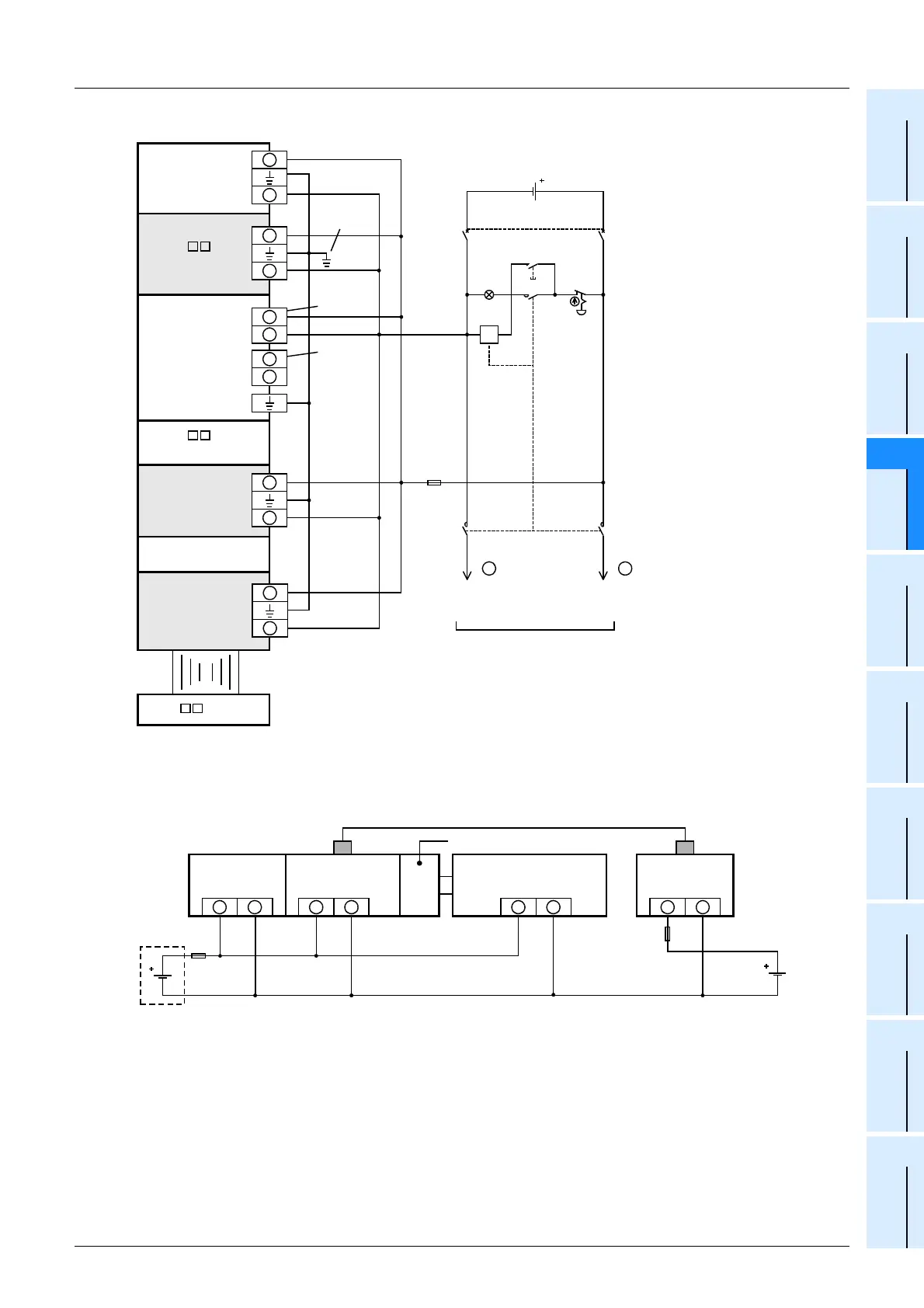
• Example of the FX3UC-MT/DSS
2. Caution on connecting the minus line (when using two or more external DC power supplies)
When supplying power from two or more power supply units due to insufficient capacity of each DC power
supply unit, connect the minus line of each power supply unit as shown in the figure below.
FX
3UC
-
MT/DSS
FX
2NC
/FX
3UC
Special function
block
FX
3UC
-1PS-5V
+
-
+
-
+
-
FX
2N
- EX-ES/UL
Class D
grounding
*1
Fuse
MC
PL
Power supply ON
Emergency
stop
24V DC
MC
MC
MC
FX
2NC
Output
extension block
Power supply for loads to
be connected to PLC
output terminals
As for the details of emergency stop operation, see "DESIGN
PRECAUTIONS" at "Safety Precautions" field.
Special adaptor
(Alalog)
+
-
24V DC
-
24V DC
+
FX
2NC
-CNV-IF
or
FX
3UC
-1PS-5V
+
-
*1 The grounding resistance should
be 100
Ω
or less.
*2 The power supply input is only for
the FX
3UC
-1PS-5V.
*3 The same power source for the
main unit, extention power supply
unit and special function unit/block
is preferable. When using the
different power source from the
main unit, turn ON the perepheral
devices' power simaltaneously, or
earlier than the main unit's. When
turning OFF the power, confirm the
safety of the system, and then turn
OFF the power of the PLC
(including special extension
equipment) at the same time.
*2
*3
+
-
Power
connector
Power
crossover
connector
FX
2NC
- EX-DS,
FX
2NC
-16EX-T-DS
Circuit Protector
*3
*3
*3
*3
+
-
+
-
+
-
+
-
Main unit
FX
2NC
-CNV-IF
FX
0N
/FX
2N
/FX
3U
Special
function units/blocks
GOT
24V
DC
24V DC
Communication cable
Fuse
Fuse
Special adaptor
(Analog)
 Loading...


