150
FX3UC Series Programmable Controllers
User’s Manual - Hardware Edition
5 Input Specifications and External wiring
5.4 AC input [FX2N-8EX-UA1/UL, FX0N-8EX-UA1/UL]
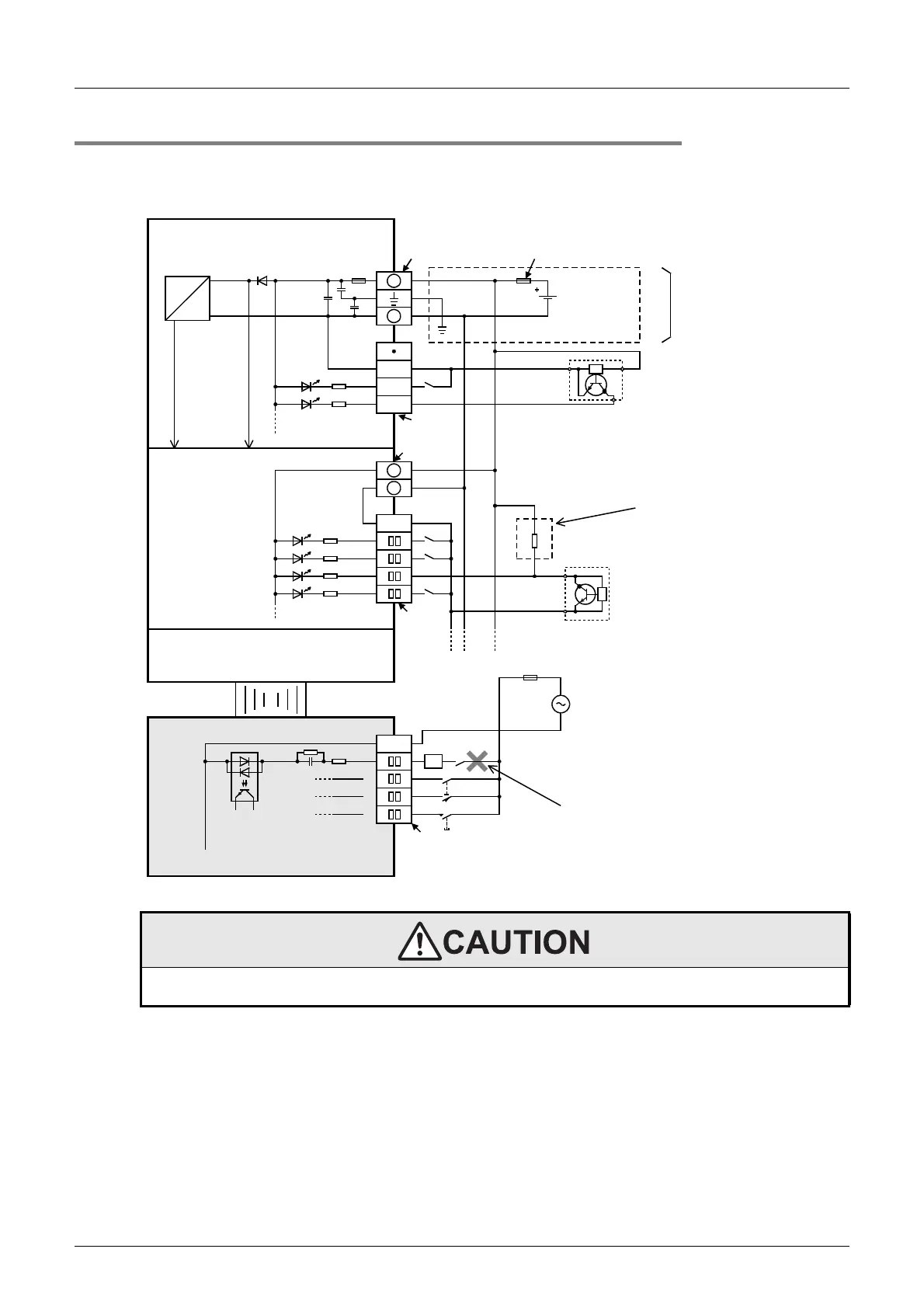
5.4.3 Example of external wiring
Do not bind or lay wires near the AC input wiring and/or DC input wiring.
Assure a distance of 100mm (3.93") or more between the wires. Without wire separation, wires are easily
affected by noise and power surges.
WIRING PRECAUTIONS
• Before cleaning or retightening terminals cut off all phases of the power supply externally.
Failure to do so may cause electric shock.
FX
2N
-8EX-UA1/UL
FX
3UC
-32MT/D
+
-
COM
X000
X001
5V 24V
FX
2NC
extension block
(Dedicated to sink
input types only)
COM
X
0
X
1
X
2
X
3
+
-
4.3k
Ω
FX
2NC
-CNV-IF
24V DC
Input
terminal
Handle the power supply
circuit correctly in
accordance with Chapter
4 "Power supply
specifications and
external wiring."
For an input device having a
parallel resistance or a
two-wire proximity switch, a
bleeder resistance may be
required.
(Refer to Subsection 5.2.4.)
COM
X
1
X
2
X
3
X
4
. . . . .
Fuse
Do not take input signals from loads
generating surge.
DC/DC
converter
DC
DC
Input
terminal
Input
impedance
*
* Class D grounding
The grounding resistance should be
100
Ω
or less.
Power
connector
Fuse
Power
connector
Input
terminal
MC
Photocoupler
Photo-
coupler
Photo-
coupler
Three-
wire
sensor
Two-wire
proximity
sensor
 Loading...


