157
FX3UC Series Programmable Controllers
User’s Manual - Hardware Edition
5 Input Specifications and External wiring
5.5 High-speed Counters (C235 to C255)
1
Outline
2
External
Dimensions
3
Generic
Specifications
4
Power Supply
Specifications
5
Input
Specifications
6
Output
Specifications
7
Examples of
Wiring for
Various Uses
8
Terminal Block
9
CC-Link/LT
Master FX
3UC
(LT only)
10
Display module
FX
3UC
(LT only)
Operation status of hardware counter/software counter
*1. Cleared when the PLC mode switches from STOP to RUN.
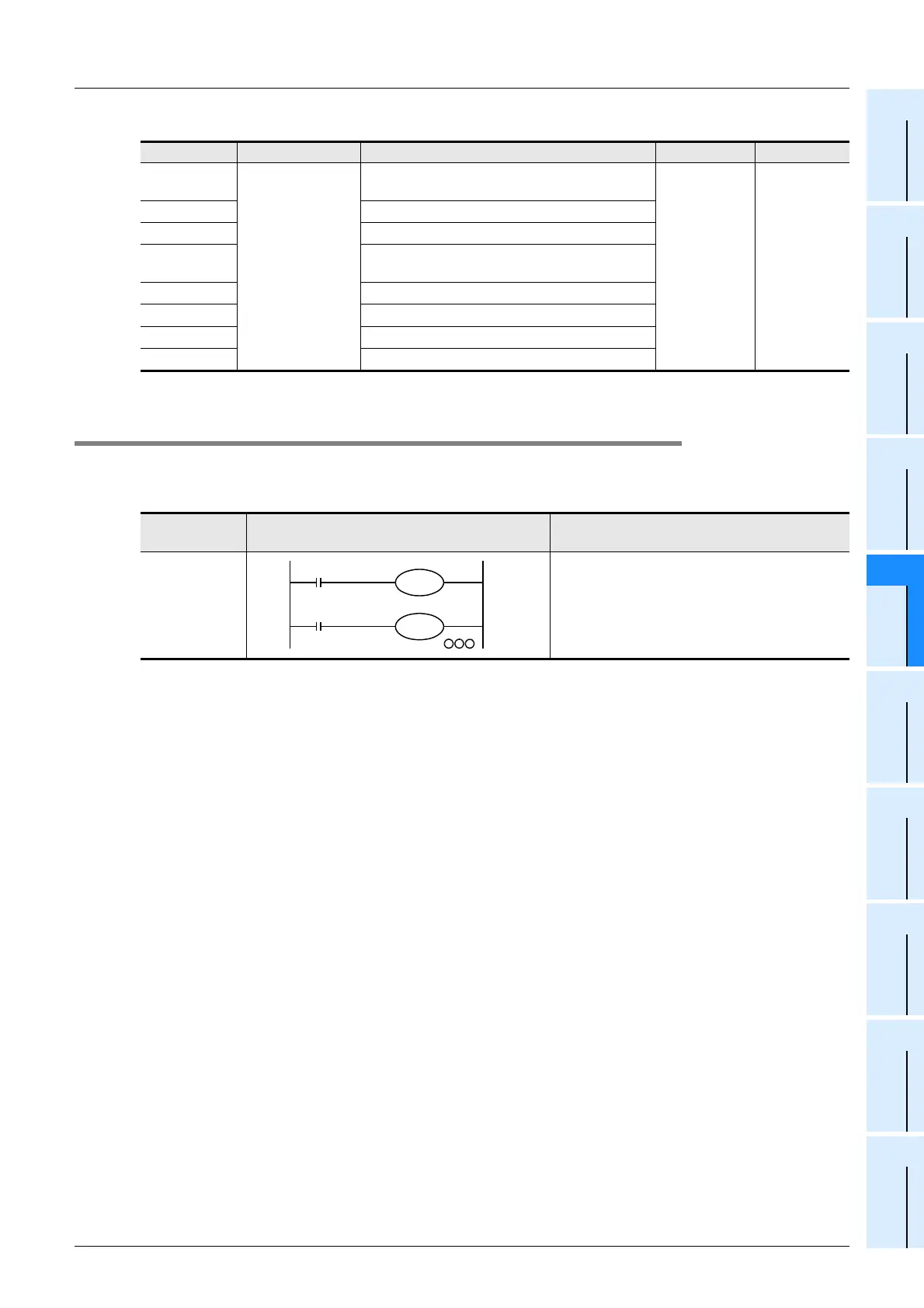
5.5.5 [Function switching] switching of logic of external reset input signal
The external reset input for the counters C241 to C245, C247 to C250 and C252 to C255 normally resets the
counters when it is turned ON. If the logic is inverted by the following program, the counters are reset by
turning the external reset input to OFF.
Cautions in inverting the logic of the external reset input signal
Although C253 is a hardware counter, it is switched to a software counter by inverting the logic of the external
reset input signal.
Device No. Name Description ON OFF
M8380
*1
Operation status
Operation status of C235, C241, C244, C246,
C247, C249, C251, C252 or C254
Software
counter
Hardware
counter
M8381
*1
Operation status of C236
M8382
*1
Operation status of C237, C242 and C245
M8383
*1
Operation status of C238, C248, C248(OP),
C250, C253 or C255
M8384
*1
Operation status of C239 or C243
M8385
*1
Operation status of C240
M8386
*1
Operation status of C244(OP)
M8387
*1
Operation status of C245(OP)
Counter No.
Inversion of logic of external reset input
signal
Details of change
C241 to C245
C247 to C250
C252 to C255
The logic of external reset input is inverted to
reset the counters when the input is turned OFF.
(The logic for all applicable counter numbers is
inverted.)
M8388
M8389
C241
K
 Loading...


