163
FX3UC Series Programmable Controllers
User’s Manual - Hardware Edition
5 Input Specifications and External wiring
5.5 High-speed Counters (C235 to C255)
1
Outline
2
External
Dimensions
3
Generic
Specifications
4
Power Supply
Specifications
5
Input
Specifications
6
Output
Specifications
7
Examples of
Wiring for
Various Uses
8
Terminal Block
9
CC-Link/LT
Master FX
3UC
(LT only)
10
Display module
FX
3UC
(LT only)
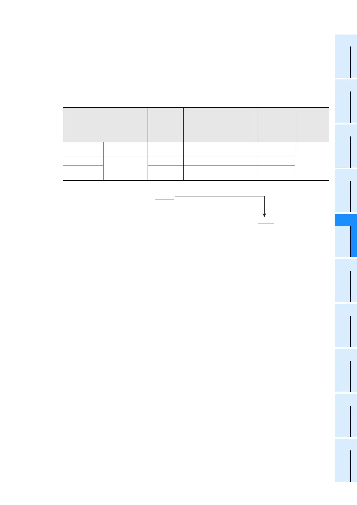
1) Calculation of overall frequency
The overall frequency is calculated using the above table according to the high-speed comparison
instructions being used in the program.
Overall frequency ≥ Sum of "response frequency of high-speed counter × Magnification for
calculation of overall frequency"
2) Example of calculation
When only the HSZ instruction is used six times in a program, the frequency is calculated by the formulas
shown in the "Only HSZ instruction" column in the above table.
High-speed counter No. to be
used
Input
frequency
Calculation of max.
response frequency
Magnification
for
calculation of
overall
frequency
Instruction
to be used
C237
Operation as
software counter
20kHz 30 - 6(times) = 24kHz
× 1
HSZ instruc-
tion is used
six times.
C241
Software counter
10kHz 30 - 6(times) = 24kHz
× 1
C253 (OP)
[
4 edge count]
2kHz {30 - 6(times)} / 4 = 6kHz
× 4
1) The overall frequency is calculated as shown below because HSZ instruction is used six times.
Overall frequency = 50 - 1.5
×
6 = 41kHz
2) The sum of the response frequencies of the high-speed counters used is
calculated as shown below.
"20kHz
×
1[C237]" + "10kHz
×
1[C241]" + "2kHz
×
4[C253(OP)]" = 38kHz
≤
41kHz
 Loading...


