209
FX3UC Series Programmable Controllers
User’s Manual - Hardware Edition
7 Examples of Wiring for Various Uses
7.8 Seven Segment with Latch [SEGL (FNC 74)/BCD (FNC 18)]
1
Outline
2
External
Dimensions
3
Generic
Specifications
4
Power Supply
Specifications
5
Input
Specifications
6
Output
Specifications
7
Examples of
Wiring for
Various Uses
8
Terminal Block
9
CC-Link/LT
Master FX
3UC
(LT only)
10
Display module
FX
3UC
(LT only)
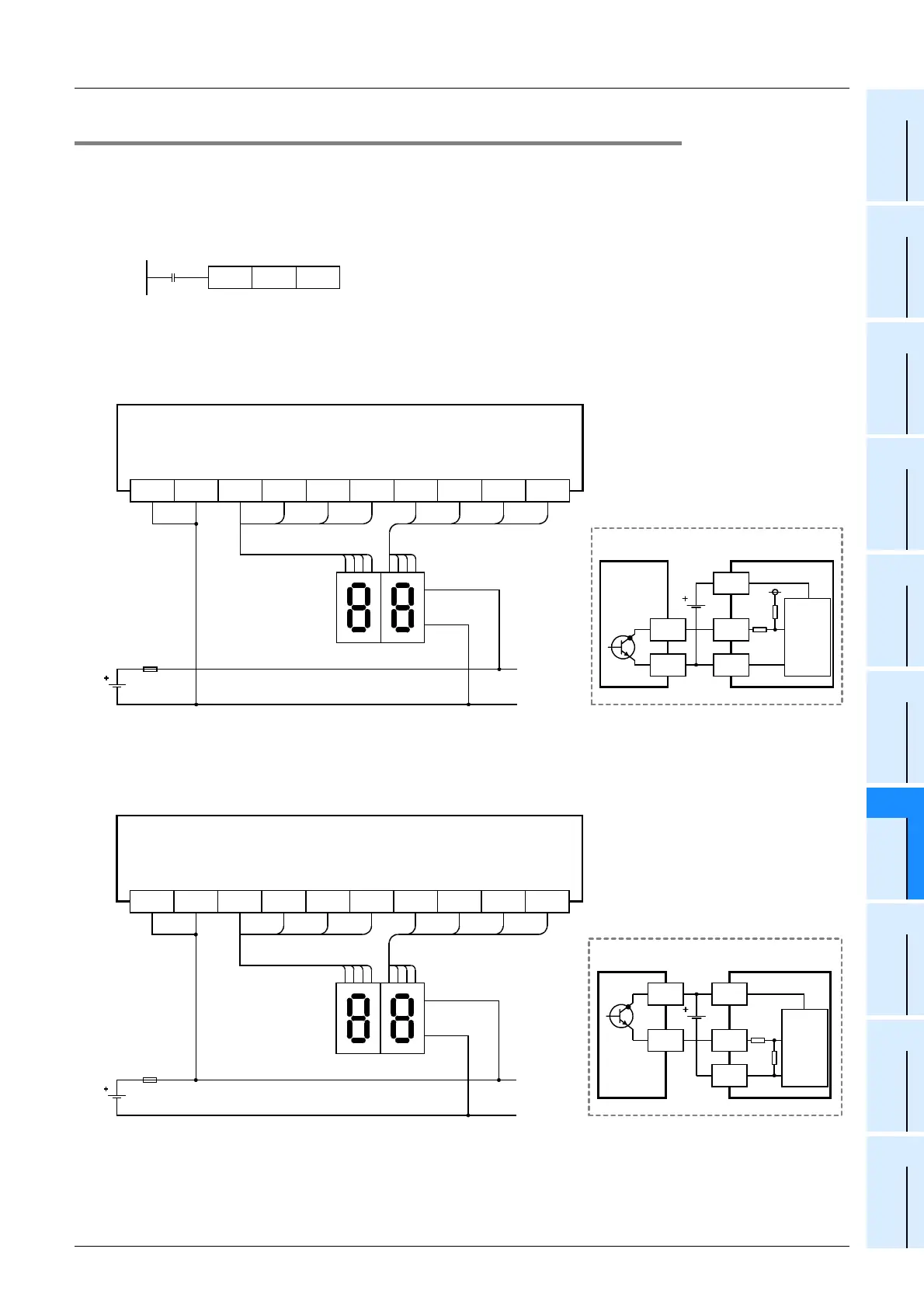
7.8.2 When BCD instructions are used
This subsection gives examples of wiring for displaying the current value of D100 on the 2-digit 7-segment
display.
1. Main unit
Example of program
Example of wiring
1) In the case of sink wiring
Use the sink only input, sink only output type main unit.
The wiring example is the FX
3UC-32MT/D or FX3UC-32MT-LT.
2) In the case of source wiring
Use the sink/source common input, source only output (transistor output) type main unit.
The wiring example is the FX
3UC-32MT/DSS.
BCD
M8000
D100
K2Y010
Y010COM1 Y011 Y012 Y013 Y014 Y015 Y016 Y017
12481248
8421 8421
Signal
-
Internal
circuit
7-segment display
+
Y
COM1
PLC
7-segment display to be used for sink wiring
(in the case of transistor output)
COM1
FX
3UC
-32MT/D
FX
3UC
-32MT-LT
Transistor output (sink)
*
* Use a 7-segment display with a latch and a built-in BCD decoder.
Fuse
Y010+V0 Y011 Y012 Y013 Y014 Y015 Y016 Y017
12481248
8421 8421
+V0
FX
3UC
-32MT/DSS
Transistor output (source)
*
* Use a 7-segment display with a latch and a built-in BCD decoder.
Fuse
Signal
-
Internal
circuit
7-segment display
+
Y
PLC
+V0
7-segment display to be used for source wiring
(in the case of transistor output)
 Loading...


