219
FX3UC Series Programmable Controllers
User’s Manual - Hardware Edition
8 Terminal Block Specifications and External Wiring
8.4 Installation Work
1
Outline
2
External
Dimensions
3
Generic
Specifications
4
Power Supply
Specifications
5
Input
Specifications
6
Output
Specifications
7
Examples of
Wiring for
Various Uses
8
Terminal Block
9
CC-Link/LT
Master FX
3UC
(LT only)
10
Display module
FX
3UC
(LT only)
8.4 Installation Work
→ Refer to Section 3.2 for installation location.
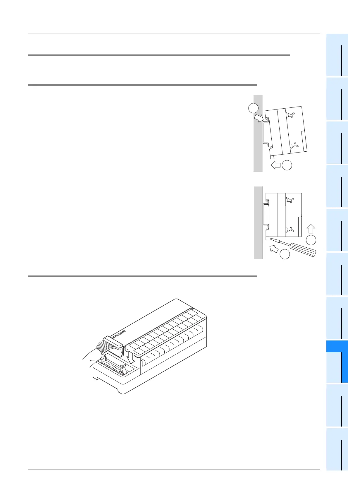
8.4.1 Mounting/Removal
1. Mounting method
1) Turn OFF all power supplies connected to the PLC, input/output devices,
and terminal blocks.
2) Align the top side of the "DIN rail mounting groove" (refer to
c at right)
3) Press the product onto the DIN rail (refer to
d
at right).
2. Removal method
1) Turn the power supply OFF.
2) Disconnect the wiring and input/output cables.
3) Place a flathead screwdriver against the DIN rail mounting hook in the
posture shown (refer to
c at right)
4) Move the flathead screwdriver in direction shown at right (refer to
d
at
right) to detach the DIN rail mounting hook from the DIN rail.
5) Remove the product from the DIN rail.
8.4.2 Input/output cable connection
The terminal block’s CN1 and CN2 connectors comply with the MIL-83503 standard.
→ Refer to Section 3.11 for input/output cable information.
1
2
1
2
Input/output cable
Terminal block
 Loading...


