32
FX3UC Series Programmable Controllers
User’s Manual - Hardware Edition
1 Outline
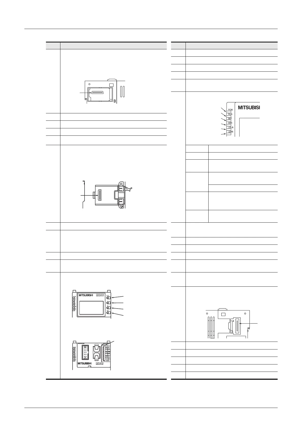
1.2 Part names
No. Description No. Description
[1]
Memory cassette dummy cover
Memory cassette or Memory
cassette dummy cover
[12]
"ESC" button
[13]
"-" button
[14]
"+" button
[15]
"OK" button
[16]
DIP switches for setting CC-Link/LT master
function
[17]
Display LEDs
[2]
Memory cassette connecting connector
[3]
Special adapter connecting hooks
[4]
Special adapter connecting holes
[5]
Expansion board fixing holes
[6]
Expansion board dummy cover
When expansion board or expansion board dummy
cover is removed
POW LED On while power to the PLC is on.
RUN LED On while the PLC is running.
BAT LED
Lights when the battery voltage
drops.
ERR LED
Flashing when a program error
occurs.
Lights when a CPU error occurs.
L RUN
On while data link is being
executed
(CC-Link/LT built-in master)
L ERR
On while data link being error
(CC-Link/LT built-in master)
[7]
Expansion board connecting connector
[18]
FX3UC/FX2NC Extension block connecting
hooks
[8]
Special adapter connector cover
Connectors are not provided when expansion board
is not used.
[19]
Input connector
[20]
Output connector
[9]
DIN rail mounting hooks
[21]
Peripheral device connector (RS-422)
[10]
DIN rail mounting groove
[DIN rail:DIN46277(35mm(1.38")wide)]
[22]
RUN/STOP switch
[11]
Display Module
When display module is removed
[23]
FX3UC/FX2NC Extension block connecting
holes
[24]
FX3UC/FX2NC Extension block connector
cover
Extension block connector cover
[25]
FX3UC/FX2NC Extension block connector
[26] Nameplate
[27]
CC-Link/LT interface connector
[28]
Power connector for main unit
[29]
Battery cover
[2]
Green
Green
Red
Red
Green
Red
[7]
[12]
[13]
[14]
[15]
[16]
[25]
 Loading...


