CHASSIS INFORMATION - 10
174
CAY M A N 2 0 0 7
CHASSIS - INTRODUCTION
This section contains information and
instructions regarding various components of the
motorhome chassis. Follow the guidelines and
procedures to help understand and operate the
motorhome. Complete instructions for engine
and transmission are located in their respective
operator’s manual included in the Owner’s
Information File Box.
WARNING:
When welding is involved for
motorhome repair or modification,
only qualified, experienced technicians
should weld on the chassis. Improper
welding procedures and materials
may weaken the assembly or result in
damage that is not obvious and may not
cause an immediate problem or failure.
Unauthorized modifications or repairs
to the chassis could result in a forfeiture
of warranty coverage.
DANGER:
Due to the sensitive nature of the
electronics on the chassis, the following
precautions are required to protect
electrical components in the motorhome
chassis:
1. Disconnect the (+) positive and (-)
negative battery connection.
2. Cover electronic control components
and wiring to protect from hot
sparks.
3. Disconnect the terminal plugs from
the engine Electronic Control Unit,
located on the curbside side of the
engine block.
4. Disconnect all the plugs from the
transmission Electronic Control Unit,
located between the frame rails.
5. Disconnect the wiring from the
alternator.
6. DO NOT connect welding cables to
electronic control components.
7. Attach the welding ground cable no
more than two feet from the part to
be welded.
The Roadmaster chassis is a semi-monocoque
design using all tubular steel. The semi-
monocoque design provides greater structural
integrity and overall uniform stress distribution.
The Roadmaster chassis includes four outboard
air springs and four Monroe shock absorbers.
The location of the air springs and shock
absorbers combined with the semi-monocoque
chassis provides the smoothest ride, best
handling and trouble free service while
delivering top notch drivability. The chassis also
includes a three-point hydraulic leveling system.
The front and drive axles are af xed in the
chassis with trailing links. A panhard bar
attached to the axle and frame prevents side
motion of the axle in the chassis. The suspension
control arms attach to the frame through
bushings, which require no lubrication. The
preset suspension ride height automatically
maintains proper suspension height throughout
the load range.
The towing receiver is rated at 7,000 lbs.
towing weight and 700 lbs. tongue weight.
AIR SUPPLY SYSTEM
The air compressing system on the motorhome
includes: a compressor, governor, dryer,
front tank and rear tank. The compressed
air system operates several items, including
brakes, suspension, air horns and air gauge.
The air system is charged by a gear driven
air compressor mounted on the engine. As
engine speed increases, compressed air output
increases. When the air is compressed, heat
is generated. Heat dissipates as the air is
discharged from the compressor. Moisture
condenses in the compressed air as it cools and
enters the air dryer to be ltered. The ltered
air charges the front air tank, which is divided
in to a wet and dry side. The compressed air
enters the wet side before entering the dry side.
A discharge line from the dry side of the front
air tank charges the rear air tank. Discharge lines
use in-line check valves to prevent a back ow
of compressed air.
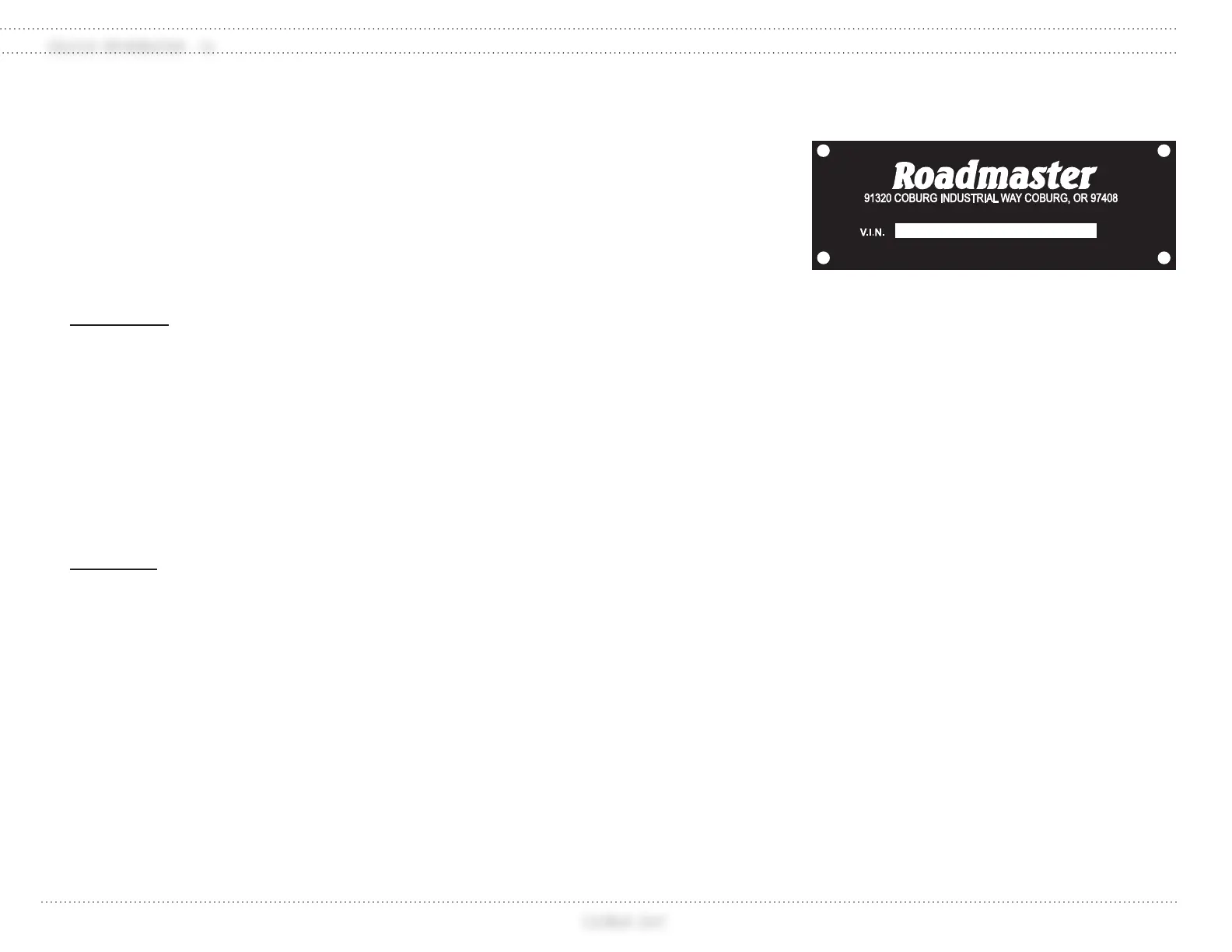
100168b
Tag located on curbside frame behind front
wheel and in generator compartment.