CHASSIS INFORMATION - 10
182
CAY M A N 2 0 0 7
ABS SYSTEM (ANTI-LOCK BRAKES)
The motorhome is equipped with an anti-
lock braking system (ABS) and automatic
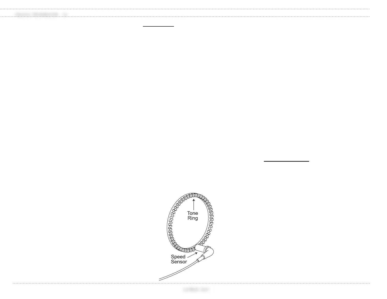
traction control system (ATC). The ABS system
monitors wheel rotation speeds by using a 100-
tooth magnetic tone ring mounted to the hub.
Revolving with the wheel, the magnetic tone
ring is polarized giving positive and negative
pulsations. A stationary sensor is mounted
adjacent to the tone ring to monitor magnetic
pulses. The pulses are monitored by the ABS
electronic control unit (ECU).
The ECU monitors all wheel sensors at the
rate of 100 times per second. The ECU controls
Pressure Modulator Valves. Pressure Modulator
Valves have two electric-over-air solenoids,
a hold solenoid and a release solenoid. The
modulator valves are open under normal
braking, allowing a straight through air signal
from the treadle valve to the brake chamber.
Should a wheel lose traction under a braking
application, the ECU will energize the hold
solenoid of the Pressure Modulator Valve to
interrupt the air signal from the treadle valve to
the brake chamber. The release solenoid vents
the existing air signal, at the brake chamber to
the atmosphere, allowing the skidding tire to
regain traction. Skidding tires have less traction.
It is possible, under certain conditions, to have
the wheel(s) skid with a normal functioning
ABS system.
The ABS itself does not apply additional
braking power. The purpose of the ABS is to
limit wheel lock and decrease stopping distance.
Cautious driving practices and maintaining
adequate safe distance when following vehicles
is the key to safe vehicle operation.
WARNING:
The ABS/ATC system is designed to
increase tire to road surface traction but
cannot overcome naturally occurring
laws of physics. The ABS/ATC system,
combined with safe driving practices,
will reduce the possibility of wheel skid
and loss of lateral stability.
ABS Component Function:
Speed sensors and tone rings on each
wheel monitor wheel rotation.
Each speed sensor communicates wheel
rotation pulses to the Electronic Control
Unit.
The ECU receives the speed sensor
signal pulses to calculate speed and
acceleration rates of each wheel.
Based on the speed sensor input, the
ECU detects impending wheel lock
and operates the ABS Modulator
Valves required for proper control. The
Modulator Valves are operated in the
Air, Release or Hold modes to regulate
air pressure to the brake chambers.
Braking force is applied at a level which
minimizes the stopping distance while
maintaining as much lateral stability as
possible.
ABS Warning Light:
The ABS will perform a dash indicator lamp
check and self-diagnostic test each time the
ignition is switched to the on position.
When the ignition is turned on, the ABS
indicator illuminates momentarily (3
seconds) verifying the self-diagnostic
test. If the ABS indicator light remains
on, or illuminates while the motorhome
is being operated, this indicates a fault
in the anti-lock brake system. This fault
will not affect normal service braking.
The motorhome will need to go to a
service center to repair the problem.
INFORMATION:
If a fault code occurs, call a Bendix
service locator at 1-800-247-2725 and
take the motorhome to the nearest
repair facility.
ABS Diagnostic Button:
By properly actuating the ABS diagnostic
button, system con guration codes and fault
codes can be retrieved as ashed sequences on
the ABS warning light. System con guration
codes are sequences of six ashed digits while
fault codes are sequences of two ashed digits.
Refer to an authorized Bendix service center
for a list of code sequences. If the Diagnostic
button is not pressed correctly for a speci c
readout, stop and start over at the beginning of
the procedure.
090307