2 Ensure the connector on the display flex, encoder flex, and side control flex are not damaged
during the assembly.
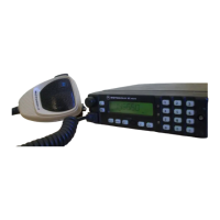
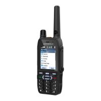
3 Align the main PCB to the front housing by using the two pin guide on the front housing. Use the
Torx Driver to screw the main PCB to the front housing.
CAUTION: Ensure the pogo pin is not deformed during assembly.
MN006362A01-AL
Chapter 7 : Radio Disassembly and Reassembly
138
 Loading...