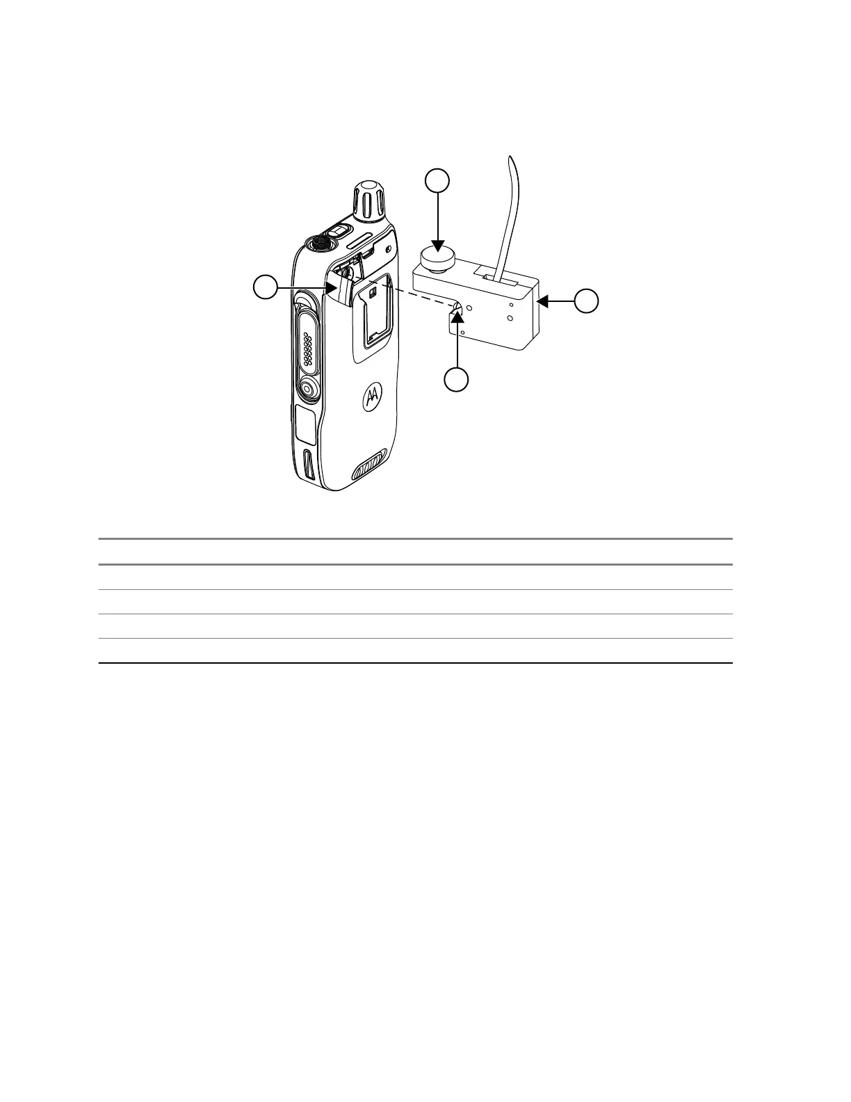
Figure 6: RF Block Insertion
Number Description
1 VA connector seal
2 RF plug
3 RF block
4 Thumb screw
4.1.2
Disassembling Procedures for Alternative Test Setup
Procedure:
1 Loosen the screw completely by turning the screw counter-clockwise.
2 Press the RF block towards the Back Cover slot during the screw removal until the screw is fully
loosen to avoid any damage to the RF plug.
3 Gently remove the RF block horizontally backwards. Be careful not to exert any side force to the
RF plug before it is fully removed from the chassis slot.
Example:
MN006362A01-AL
Chapter 4 : Test Setup and Testing
34