Section 75 00-02-0878
2013-03-07 - 125 -
Cummins After Treatment
If Cummins After Treatment equipment is installed in the exhaust line and the system is
connected to the ECU then indicators from the treatment system can be read over the J1939
link and some regeneration can be controlled.
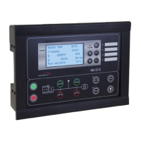
The table shows lamps and status indicators from the after treatment. The states can be
reached through M-logic and can be shown on a FW Murphy display unit.
Status indicator
particulate
filter
regeneration
Diesel
particulate
filter status
Particulate
filter lamp
High
exhaust
system
temp.
Regenera
- tion
disabled
State
Regeneration
not
-
x
- - -
Regeneration
lowest
lev
el
-
x
- - -
Regeneration
moderate
level
-
x
- - -
Regeneration
highest
level
-
x
- - -
Besides the lamp and status indicators two after treatment switches for control of the
regeneration are available. These can be reached through M-logic in the command group.
1. Cummins particulate filter manual (non-mission) regeneration initiate.
2. Cummins particulate filter regeneration.