Section 75 00-02-0878
2013-03-07 - 16 -
Underfrequency (81)
Voltage unbalance (60)
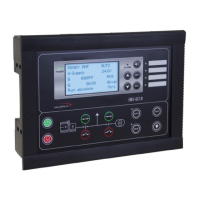
Display
Push-buttons for start and stop
Push-buttons for breaker operations
Status texts
M-Logic
Simple logic configuration tool
Selectable input events
Selectable output commands
Terminal
Strip
Overview
Reference to Installation Instructions
Information about terminal strip overview and rear side controller view can be found in
the "Installation Instructions", which is located on FW Murphy website under
documentation for EMS-GC10.
Measurement Systems
EMS-GC10 unit is designed for measurement of voltages between 100 and
690Vpp AC. For further reference, the AC wiring diagrams are shown in the
Installation Instructions. In parameters 9130, 9131 the measurement principle
can be changed between three-phase, single phase and split phase.
IMPORTANT: Configure EMS-GC10 to match the correct
measuring system. When there is a doubt, contact the
switchboard manufacturer for information about the required
adjustment.
NOTE: EMS-GC10 unit has four sets of nominal generator
settings, which can be enabled individually in the different
measurement systems.