Section 75 00-02-0878
2013-03-07 - 166 -
Operators
Two operators are available, and they can be: “OR” (any operator activates the function
output), “AND” (all activated operators must have status ON to activate the function
output).
Enable
the
Rule
If this tick box is not ticked, the logic in question will not operate.
Output
This is the selection of the reaction of the system upon activation of the function. Note
that the output has a delay function. If set to 0 s (default), there is no delay.
Commands
Command to the EMS-GC10 unit, for example,, select AUTO running
mode.
Virtual
events
A number of internal (virtual) events that can be activated and used in
another logic line. By using these virtual events, the number of
activating (triggering) events can be expanded from the three
available in each logic line to, in theory, an unlimited number of
events. Virtual events can also be trigged from Modbus.
Relays
Selection of a relay output. The selection of these is option-
dependent.
Inhibits
A selection of inhibit functions for the alarms. Static sync. type:
Selection between static sync. functionalities.
Possibility to force the speed/voltage control up or down for 5 sec.
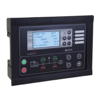
Alarm LED
The availability
of the alarm LEDs
is
dependent
on the module in
question. There are (
4)
LED’s
mounted
on the
display front.
Commands that are related to engine
communication.
Buzzer
Incorporated buzzer.
Control
of activation and deactivation
of the
buzzer (e.g., with
alarms).
CAN cmd
Command to EMS-GC10 unit
connected
to the power management
CAN line, for example
, select AUTO running mode.