NMC-64 Irrigation
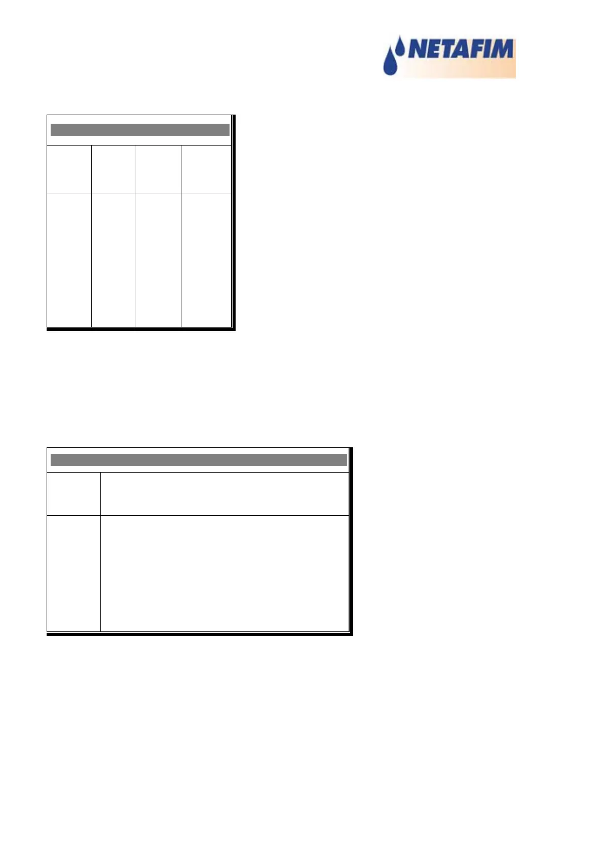
7.3 VALVE CONFIGURATION
VALVE CONFIGURATION
Valve
No.
Pump Main
Valve
Water
Meter
1
2
3
4
5
1
1
1
1
1
2
1
1
1
1
1
1
1
1
1
Associate proper equipment with each valve. The numbers on the left are valve
numbers. In the example above, valve number 1 is associated with pump 1, main
valve 2 and water meter 1.
7.4 VALVE FLOW RATE
VALVE FLOW RATE
Valve
No.
Nominal Minimum Maximum
m3/h m3/h m3/h
1
2
3
4
5
6
5.000 3.750 6.250
5.000 3.750 6.250
5.000 3.750 6.250
5.000 3.750 6.250
5.000 3.750 6.250
5.000 3.750 6.250
The NMC-64 uses cubic meters per hour when measuring the valve flow rate. The
minimum and maximum levels set on this window are levels at which the NMC-64 will
shut down valves and activate the alarm for low or high flow rates. The nominal level
is the actual rate a valve should produce. Enter appropriate values of water flow for
each valve.
Minimum/maximum levels are by default set to 25% below/above of the nominal level.
60