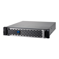
Figure 48) Viewing system status information by using SANtricity System Manager.
Controller Base Port Status LEDs
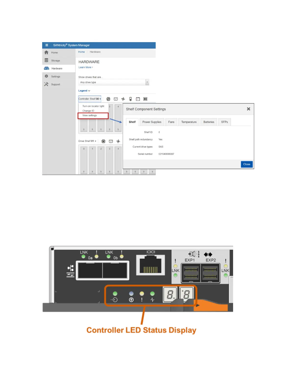
Figure 49 shows the onboard LED status indicators on the left side of the EF570 controller canister. Most
of the LEDs are lit when a fault condition exists; however, the cache active LED is lit when the cache is
active. The seven-segment LEDs provide status codes for both normal operation and fault conditions.
The dot in the first seven-segment LED is the controller heartbeat indicator, which comes on when an
intercontroller communication link has been established. The dot in the second seven-segment LED is on
to indicate a diagnostic code. Otherwise, the display indicates the shelf ID. Table 18 provides the
controller status LED definitions. The table lists the LEDs as they appear left to right in the figure.
Figure 49) Controller module and array status LEDs.