Introduction to NetApp EF570 All-Flash Arrays:
Feature Overview with SANtricity 11.50.2
© 2019 NetApp, Inc. All Rights Reserved.
Table 19) Ethernet management port LED definitions.
Ethernet management port
link state (top left)
Ethernet management port
link activity (top right)
Blinking: the link is up
with activity.
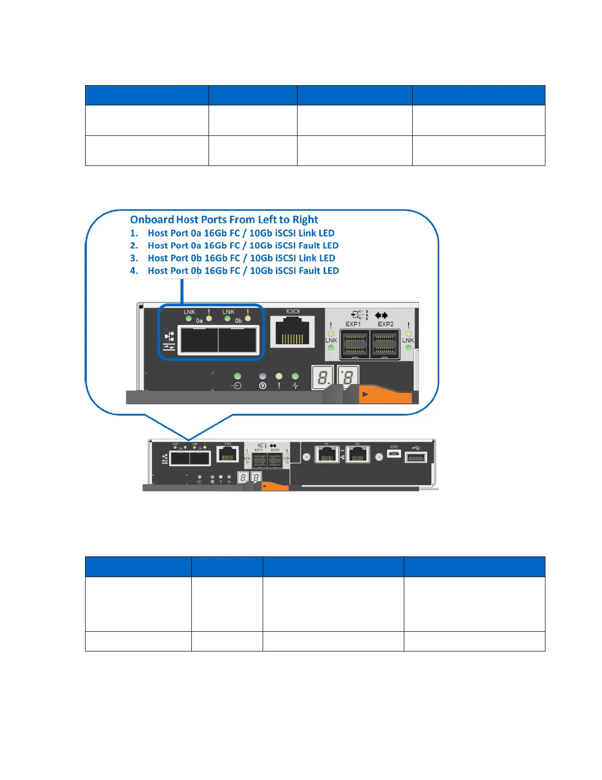
Figure 51 shows the onboard 16Gb FC or 10Gb iSCSI baseboard host port LEDs.
Figure 51) Ports 0a and 0b 16Gb FC/10Gb iSCSI baseboard host ports.
Table 20 defines the baseboard host interface port LEDs (LEDs 1 through 4 in Figure 51). These LEDs
indicate the connection status for each link between the storage system and host-side hardware.
Table 20) 16Gb FC/10Gb iSCSI baseboard host port LED definitions.
• Solid: link is up with no
activity.
• Blinking: link is up with
activity.
Port requires operator attention.