Introduction to NetApp EF570 All-Flash Arrays:
Feature Overview with SANtricity 11.50.2
© 2019 NetApp, Inc. All Rights Reserved.
Table 18) Controller base features LED definitions.
Request to locate the enclosure
is active.
Some fault exists in the
controller canister.
Blinking: controller active.
Controller is not in service.
Heartbeat (upper digit
of seven-segment LED,
dot in lower right)
Controller is not in service.
Diagnostic (lower digit
of seven-segment LED,
dot in upper left)
Seven-segment display
indicates diagnostic code.
Seven-segment display
indicates shelf ID.
• Shelf ID if diagnostic LED off.
• Diagnostic code if diagnostic
LED on.
The controller is not powered
on.
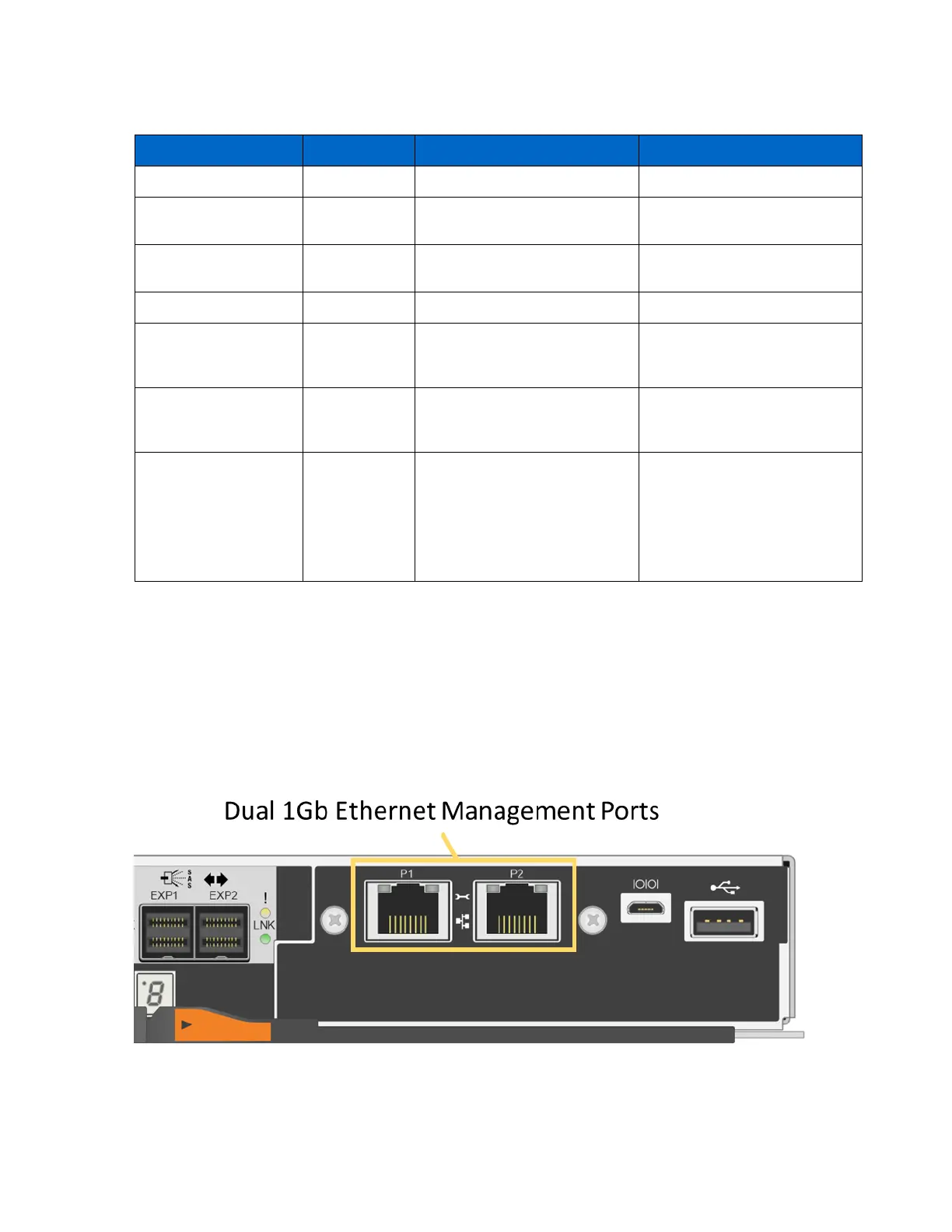
The EF570 controller has two 1GbE management ports that default to the Dynamic Host Configuration
Protocol (DHCP). If you want to use static addresses to manage the EF570, simply leave the
management ports disconnected for approximately five minutes after powering up, to allow the DHCP
feature to time out. Then, you can connect with a local PC to the default IP addresses:
• Controller A Port 1 = 192.168.128.101 Port 2 = 192.168.128.102
• Controller B Port 1 = 192.168.129.101 Port 2 = 192.168.129.102
Figure 50 shows the dual Ethernet management ports on the EF570 controller.
Figure 50) Ethernet management ports on the EF570 controller canister.
Table 19 defines the Ethernet management port LEDs. The ports are highlighted in Figure 50.