Introduction to NetApp EF570 All-Flash Arrays:
Feature Overview with SANtricity 11.50.2
© 2019 NetApp, Inc. All Rights Reserved.
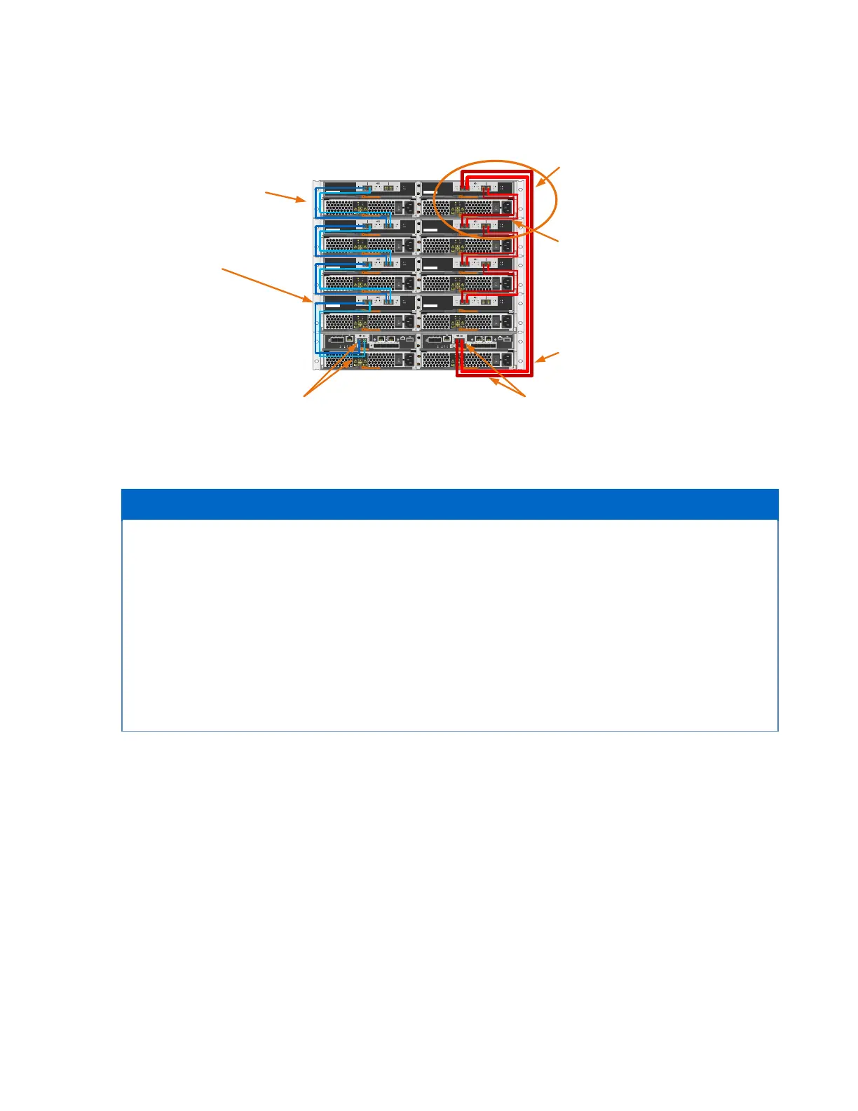
Figure 66) Drive shelf hot-add controller expansion port 2 cabling.
Plan carefully for any drive shelf hot-add activity on production storage systems. Verify that the
following conditions are met:
• The existing power infrastructure can support the additional hardware.
• The cabling plan for the new shelf does not simultaneously interrupt both SAS expansion paths for
controller A and controller B to the expansion-drive shelves.
• The new expansion port 1 path is confirmed to be valid, and the new shelf is visible in the
SANtricity management software before the expansion path 2 is disconnected and moved to the
new shelf.
Note: Failure to preserve one active path to existing drive shelves during the procedure could
potentially result in degradation/failure of LUNs during I/O activity.
7 E-Series Product Support
NetApp E-Series storage systems are identified by the serial number (SN) of the E-Series system shelf,
not the SNs of the individual controllers in the E-Series system shelf. The correct SN must be registered
for an E-Series system because only the SN of the E-Series system shelf can be used to log a support
case with NetApp.
7.1 Controller Shelf Serial Number
The EF570 storage systems are shipped preconfigured from the factory (controllers have HICs and
batteries installed, and controllers are installed in the controller shelf). The chassis serial number is
printed on a white label that is affixed to the controller shelf behind the right end cap on the front of the
chassis. The SN is identified by the text “SN,” which is shown in Figure 67.
Controller A drive expansion
port 1 and port 2 cable path
to first expansion drive shelf
A
IOM12
21
LNK LNK
43
LNK LNK
S/N: 012345678901
||||||||||||||||||||||||||||||||||||||
IOM12
21
LNK LNK
43
LNK LNK
S/N: 012345678901
||||||||||||||||||||||||||||||||||||||
IOM12
21
LNK LNK
43
LNK LNK
S/N: 012345678901
||||||||||||||||||||||||||||||||||||||
IOM12
21
LNK LNK
43
LNK LNK
S/N: 012345678901
||||||||||||||||||||||||||||||||||||||
IOM12
21
LNK LNK
43
LNK LNK
S/N: 012345678901
||||||||||||||||||||||||||||||||||||||
IOM12
21
LNK LNK
43
LNK LNK
S/N: 012345678901
||||||||||||||||||||||||||||||||||||||
IOM12
21
LNK LNK
43
LNK LNK
S/N: 012345678901
||||||||||||||||||||||||||||||||||||||
IOM12
21
LNK LNK
43
LNK LNK
S/N: 012345678901
||||||||||||||||||||||||||||||||||||||
LNK LNK
EXP1 EXP2
LNK LNK
0a 0b
P1 P2
LNK LNK
EXP1 EXP2
LNK LNK
0a 0b
P1 P2
Controller drive shelf
First expansion drive shelf
Step 2 – Move controller B
exp. port 1 and 2 to new
last shelf IOM12 exp. port
1 and 2
EF570 Shelf Hot-add
Controller B
expansion ports 1 and 2
Step 3 – Add new B-side
IOM12 exp. port 3 and 4
cables from new shelf to
previous last shelf IOM12
exp. port 1 and 2
New shelf
Controller B drive expansion
port 1 and port 2 cable path to
new expansion drive shelf
Controller A
expansion port 1 and 2