• 1/4 inch Open-ended Wrench
• 5/16 inch Open-ended Wrench
• Medium size flat head screw driver
Caution The accuracy of all test equipment (electronic or
pneumatic) used for verification or calibration procedures
should be certified annually by a testing laboratory before
use.
SETUP
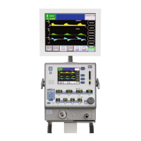
Figure 5-1 e360 Ventilator Connected to Gas Sources
1 Visually inspect the e360 ventilator for cosmetic defects,
damage or missing items.
2 Before removing the Top Cover, unplug the e360 ventilator
from the AC power and gas sources.
3 Remove the 6 screws on the Back Panel that secures the
T
op
Cover to the e360 ventilator. Remove the Top Cover, see
Section 4, “Removal of Top Cover”.
4 Reconnect the AC power to the e360 ventilator.
5 Connect both air and oxygen supply gas sources to the e360
ventilator, verify supply gas sources are at 50 ±2 psig.
6 Prior to starting the calibration procedure, verify that all test
equipment is in current calibration status.
CALIBRATION PROCEDURES
O
xygen Supply
Air Supply
5-2 SER360 A1106

 Loading...