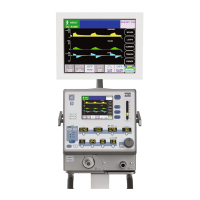
Pneumatics Calibration
NOTE: Before proceeding with the pneumatics calibration, the
Analog PCB in the e360 ventilator must be previously calibrated.
NOTE: To calibrate Air/Oxygen Inlet Regulators, and Safety
Regulator
, use Diagnostic Mode “d3”:
Manual Flow Adjustment.
Air Inlet Regulator
1 Connect the Air and Oxygen gas supplies and AC power to
the e360 ventilator.
2 Turn ON the power to the e360 ventilator.
3 Enter the Diagnostics Mode following the procedure “Entering
Diagnostics Mode” in this Section.
SECTION 5
TRANSDUCER LCD t Insp PRESSURE TOLERANCE TUBE COLOR
ID DISPLAY
XD107 Drive 0 3.00 cmH
2
O ±0.05 Orange
Pressure
XD106 Machine 2 2 0.00 cmH
2
O ±0.05 Green
XD105 Machine 1 4 0.00 cmH
2
O ±0.05 Clear
XD102 Air Gas 6 0.0 psig ±0.1 Yellow
Supply
XD103 O
2
Gas 8 0.0 psig ±0.1 Blue
Supply
ZERO SETTING
Table 5-2 Zero Offset Calibration
TRANSDUCER LCD t Insp PRESSURE TOLERANCE DESIGN TUBE
ID DISPLAY ATION COLOR
XD107 Drive 1 110 cmH
2
O ±1.0 Bottom Orange
Pressure Port
XD106 Machine 2 3 110 cmH
2
O ±1.0 Bottom Green
Port
XD105 Machine 1 5 110 cmH
2
O ±1.0 Top Port Clear
XD102 Air Gas 7 25 psig ±0.1 Top Port Yellow
Supply
XD103 O
2
Gas 9 25 psig ±0.1 Top Port Blue
Supply
GAIN SETTING
T
able 5-3 Gain Calibration
SER360 A1106 5-9

 Loading...