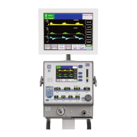
Figure 5-4 Exhalation Servo / Safety Regulators
Safety Regulator
1 While still in Diagnostics Mode “d3”, adjust Flow to 3 L/min.
2 Connect a patient circuit to the e360 ventilator as shown in
Figure 6-1. (Test lung is not needed)
3 Disconnect the patient circuit from the Exhalation V
alve, and
connect it to the Y-piece of the patient circuit, which is to form
a close loop.
4 Tee in a low pressure gauge in the patient circuit.
5 Use a flat head screw driver to adjust the Safety Regulator,
see Figure 5-4, to obtain 140 ± 5 cm2HO of “
Machine 1”
pressure displayed on LCD touch screen.
6 Verify the reading of the pressure gauge is within 2 cmH
2
O of
the value of “Machine 1” pressure.
7 Adjust Flow to 0 L/min after the calibration is completed. Then
press “
Manual Inflation” button to disable manual flow
adjustment.
The “
Message ID” will change to “13”.
Air Servo Valve: d1
Caution: Do not attempt to perform Air Servo Valve calibration
unless instructed by NMI Representative or for one of the
following conditions:
•Replacement or readjustment of Air Inlet Regulator
•
Replacement of
Air Servo Valve
•Replacement of Analog PCB
•
Replacement of Main PCB
CALIBRATION PROCEDURES
Orange
Tubing to
Exh. Servo
Val. Port “IN”
Exh. Servo Val.
Exh. Servo
R
egulator
Safety
R
egulator
5-12 SER360 A1106

 Loading...