Safety
information
Introduction
Product
Information
System
design
Mechanical
Installation
Electrical
Installation
Getting
started
Optimization Parameters
Technical
data
Component
sizing
Diagnostics
UL
Information
Unidrive M Regen Design Guide 139
Issue Number: 4
7 Getting started
7.1 Regen parameter settings
7.1.1 Switching frequency Pr 05.018 (Pr 00.041)
Set the switching frequency on the Regen drive to the required value
(3 kHz default value).
A higher switching frequency setting has the following advantages:
• Line current ripple at the switching frequency is reduced, giving
improved waveform quality.
• Acoustic noise produced by the line inductors is reduced.
• Dynamic DC bus voltage response is improved.
N
In some cases, setting the switching frequency to a value greater than
the default 3 kHz results in current derating. Refer to Chapter 10
Technical data on page 276.
7.1.2 DC bus voltage set point
The table below defines the DC Bus voltage set point levels, assuming a
tolerance of ±10 % on the given supply voltage. The minimum value is
defined as the peak input voltage plus some headroom. Headroom is
required by the drive to allow correct control of the current. It is advisable
to set the voltage below the maximum value to give more allowance for
transient voltage overshoots.
Table 7-1 DC bus voltage set point - Pr 03.005 (Pr 00.001)
The DC bus voltage set point, see Pr 03.005 (Pr 00.001), should be set
to a level that is suitable for the AC supply voltage being used. It is very
important that the Regen drive DC bus voltage set point Pr 03.005
(Pr 00.001) is set above the peak AC supply voltage by at least 50 Vac.
7.2 Regen drive sequencing
When a Regen drive is enabled, it goes through a line synchronization
sequence. During this procedure, test pulses are applied to the incoming
line to determine the voltage and phase. When it has been successfully
synchronized to the line, the DC bus voltage controller is enabled and
the DC bus voltage rises to the target voltage.
Only when all of these stages have been completed successfully is the
motoring drive enabled. If at any time there is a fault, or the Regen drive
is disabled, the motoring drive will also be disabled.
This sequence of events is important to prevent damage to the Regen
drive, motoring drive or external power circuit components.
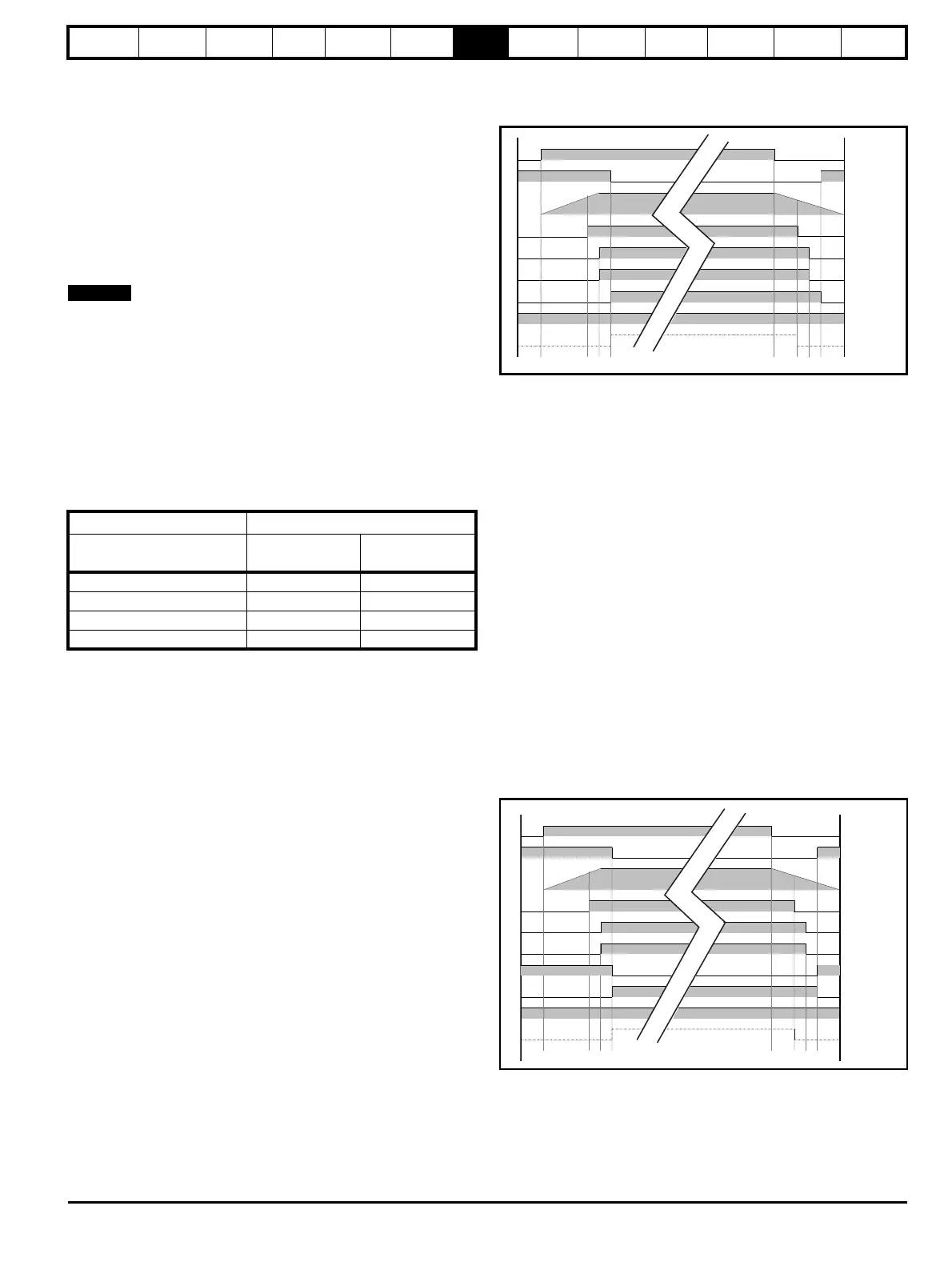
The sequence of events is as follows:
Power applied and power removed 400 V system
(refer to Figure 4-4 on page 42)
Figure 7-1 Single Regen: Single Motoring
1. K1 (main supply contactor / isolator / disconnect) is closed with
charging circuit active (K3 closed).
2. DC bus charges through the Regen drives Vac inputs L1, L2, L3
(charging circuit).
3. If the DC Bus > the UV threshold then K2 Regen drive main
contactor and Aux.2a are closed via Regen drives relay, control
terminals 41, 42.
4. K3 charging contactor is opened via K2 (Regen drive main contactor
as Aux.2b opens) and Aux.3 closes. The Regen drive enable, S1
can now be applied.
5. The Regen drive and motoring drives can be enabled (enable signal
from Regen drive to motoring drives active, control terminal 24).
6. K1 (main supply contactor / isolator / disconnect) is opened
removing power from the Regen system.
7. DC bus discharges to the UV threshold at which point the drive OK
relay becomes in-active. The Regen drives enable is removed.
The motoring drives enable signal from Regen drive becomes in-
active.
8. Regen drive main contactor, K2 is opened via the drive OK relay,
control terminals 41, 42. Aux.2a opens informing the drive that the
Regen drives main contactor K2 is open.
9. K3 charging contactor is closed and Aux.3 opens.
Power applied and power removed 400 V system
(refer to Figure 4-5 on page 44)
Figure 7-2 Single Regen: Multiple Motoring (Unidrive M Rectifier)
1. K1 (main supply contactor / isolator / disconnect) is closed with
charging circuit active (K3 closed).
2. DC bus charges through Unidrive M Rectifier (charging circuit).
3. If the DC Bus > the UV threshold then K2 Regen drive main
contactor and Aux.2a are closed via Regen drives relay, control
terminals 41, 42.
Voltage levels DC Bus voltage set-point
Supply voltage
Vac
Default
Vdc
Minimum
Vdc
200 350 350
400 700 700
575 835 835
690 1100 1100
K1
K3
Vdc
Drive OK
K2
Aux.3
Aux.2a
Aux.1
1 234 5 6 78
S1
9
K1
K3
Vdc
Drive OK
K2
Aux.3
Aux.2a
Aux.1
1 234 5 6 78
S1
9
Aux.2b

 Loading...


