Safety
information
Introduction
Product
Information
System
design
Mechanical
Installation
Electrical
Installation
Getting
started
Optimization Parameters
Technical
data
Component
sizing
Diagnostics
UL
Information
20 Unidrive M Regen Design Guide
Issue Number: 4
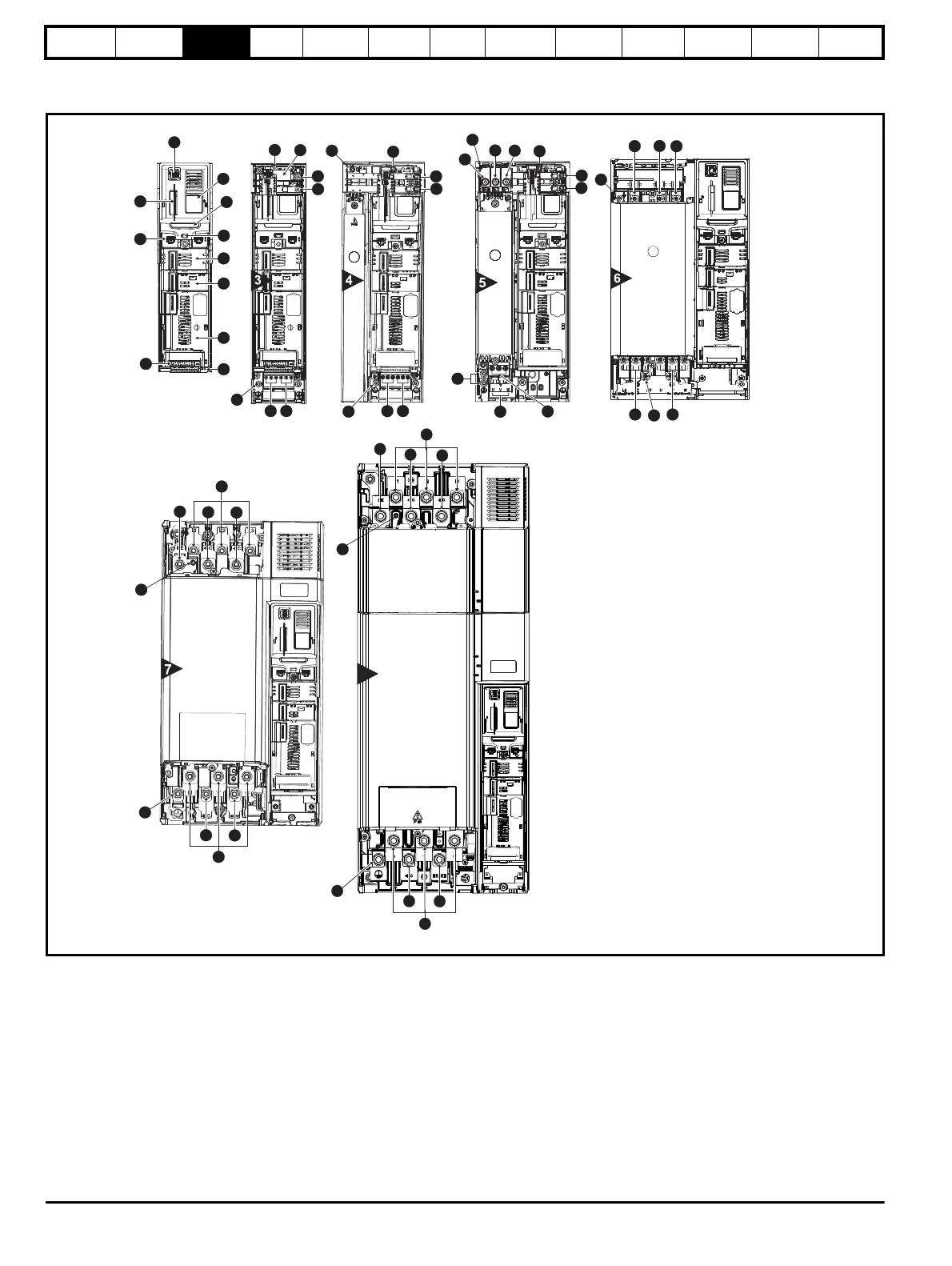
3.4 Drive features
Figure 3-3 Features of the drive sizes 3 to 8
1
2
3
4
5
6
7
8
9
9
10
11
12
13
14
15
17
16
18
12
14
15
17
16
18
15
14
15
12
11
15
15
14
18
17
16
15
14
12
17 16
18
17
14
15
18
14
12
16
18
17
18
14
16
15
16
14
12
18
8
13
13
13
13
13
Key
1. Keypad connection 6. Option module slot 2 11. NV media card slot 16. AC supply connections (U, V, W)
2. Rating label 7. Option module slot 3 12. Braking terminal 17. Charging inputs (L1, L2, L3)
3. Identification label 8. Relay connections 13. Internal EMC filter (must be removed) 18. Ground connections
4. Status LED 9. Control connections 14. DC bus output +
5. Option module slot 1 10. Communications port 15. DC bus output -

 Loading...


