Safety
information
Introduction
Product
Information
System
design
Mechanical
Installation
Electrical
Installation
Getting
started
Optimization Parameters
Technical
data
Component
sizing
Diagnostics
UL
Information
106 Unidrive M Regen Design Guide
Issue Number: 4
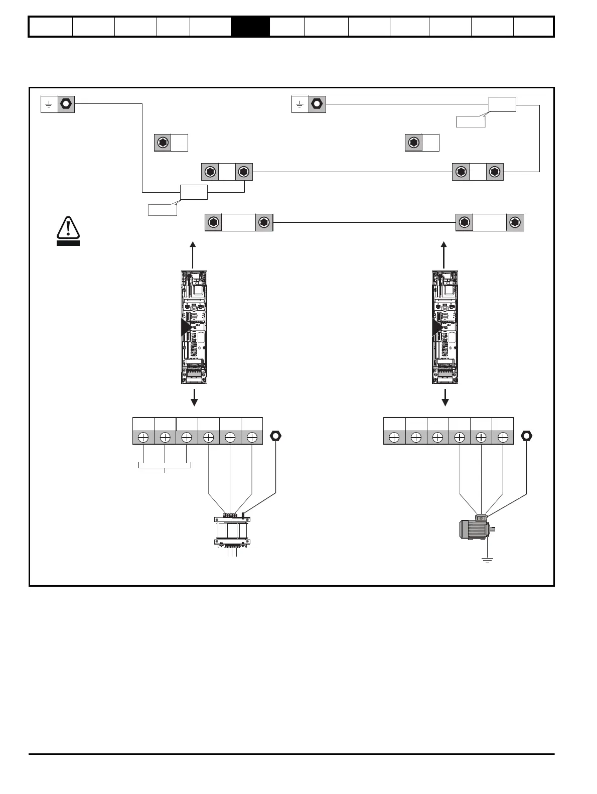
6.1 Power connections
6.1.1 AC and DC Regen connections
Figure 6-1 Unidrive M size 3 Regen drive power connections
* It is possible to connect the DC bus of a number of drives using a busbar kit (part number: 3470-0048), where DC bus fusing is not required.
See section 6.1.2 Ground connections on page 115.
L2L1 L3 U V W PE
AC supply connections
3
DC Connections*
(High current DC to motoring drive/s)
BR
+DC
-DC
Internal
EMC filter
Must be
removed
Regen drive
L1, L2, L3
(Refer to Chapter 4
)System design
Vac supply
L2L1 L3 U V W PE
Motor connections
3
BR
+DC
-DC
Internal
EMC filter
Must be
removed
Motoring drive
Motor
Optional ground
connection
CAUTION
The internal EMC filter must be removed
from all drives in the regen system
(motoring and regen).

 Loading...


