Safety
information
Introduction
Product
Information
System
design
Mechanical
Installation
Electrical
Installation
Getting
started
Optimization
Parameters
Technical
data
Component
sizing
Diagnostics
UL
Information
144 Unidrive M Regen Design Guide
Issue Number: 1
The peak of the resulting transient is
Vdc = 191680 x Pd / (vll x Kp x Kc) Volts
and the time constant of the recovery is Kp / 30520 seconds.
where:
Pd is the transient change of power flow
vll is the line to line supply voltage
Kp = Voltage Controller Proportional Gain Kp (03.006)
Kc = Full Scale Current Kc (11.061)
For example, if Pd = 7.5 kW, vll = 400 V, Kp = 4000, Kc = 38.222 A then
Vdc = 23.5 V and the time constant is 131 ms.
In the example given there is a very rapid change of power flow.
The transient DC bus voltage change can be substantially reduced by
introducing a time constant into the power transient. For example a filter
could be included between the speed controller and current controller in
the motor drive with Current Reference Filter 1 Time Constant (04.012).
A time constant of 20 ms reduces the voltage transient by 25 % and a
time constant of 40 ms reduces the voltage transient by 50 %. In most
cases it is not desirable to reduce the performance of the motor drive,
and so as already mentioned the best solution is to use a power feed
forward term from the motor drive.
So far the discussion has been related to the DC bus voltage controller
gain, however, the controller provides the real current reference to the
Regen drive current controllers, and so the current controller gains affect
the response of the voltage controller. If the default voltage controller
gain is used and it is possible to obtain a stable response from the
current controllers with their default gains then the voltage controller
response will be stable. However, in some cases it will be necessary to
reduce the current controller gains to make these controllers stable,
in which case it is likely that the voltage controller gain will need to be
reduced to make this controller stable.
It is possible to disable the DC bus voltage controller by setting Voltage
Controller Proportional Gain Kp (03.006) to zero. This sets both the
proportional and integral gains to zero. Once the controller is disabled
the flow of power through the Regen drive can be defined using the
power input parameters (Power Input 1 (03.010), Power Input 2
(03.013), Power Input 3 (03.014), Power Input kW (03.018)) or
Active Current (04.002). This method of control can only be used if the
DC bus voltage is defined at a voltage above the level of the rectified AC
supply to the Regen drive by another system connected to the DC
terminals.
8.5 Power factor correction (Pr 04.008)
Reactive Current Reference (04.008) can be used to define a level of
reactive current other than the default value of zero, so that the Regen
drive can be made to produce or consume reactive power.
Reactive Current Reference (04.008) defines the level of reactive
current as a percentage of the Rated Current (05.007). Positive reactive
current produces a component of current flowing from the supply to the
Regen that lags the respective phase voltage, and negative reactive
current produces a component of current that leads the respective
voltage.
The variable maximum applied to Reactive Current Reference (04.008)
is used to ensure that the total current does not exceed the maximum
allowed. If the current limits are at their maximum values then no
reactive current is allowed and
VM_REGEN_REACTIVE_REFERENCE[MIN] = 0 and
VM_REGEN_REACTIVE_REFERENCE[MAX] = 0. As the Final Current
Limit (04.018) is reduced then more reactive current is allowed.
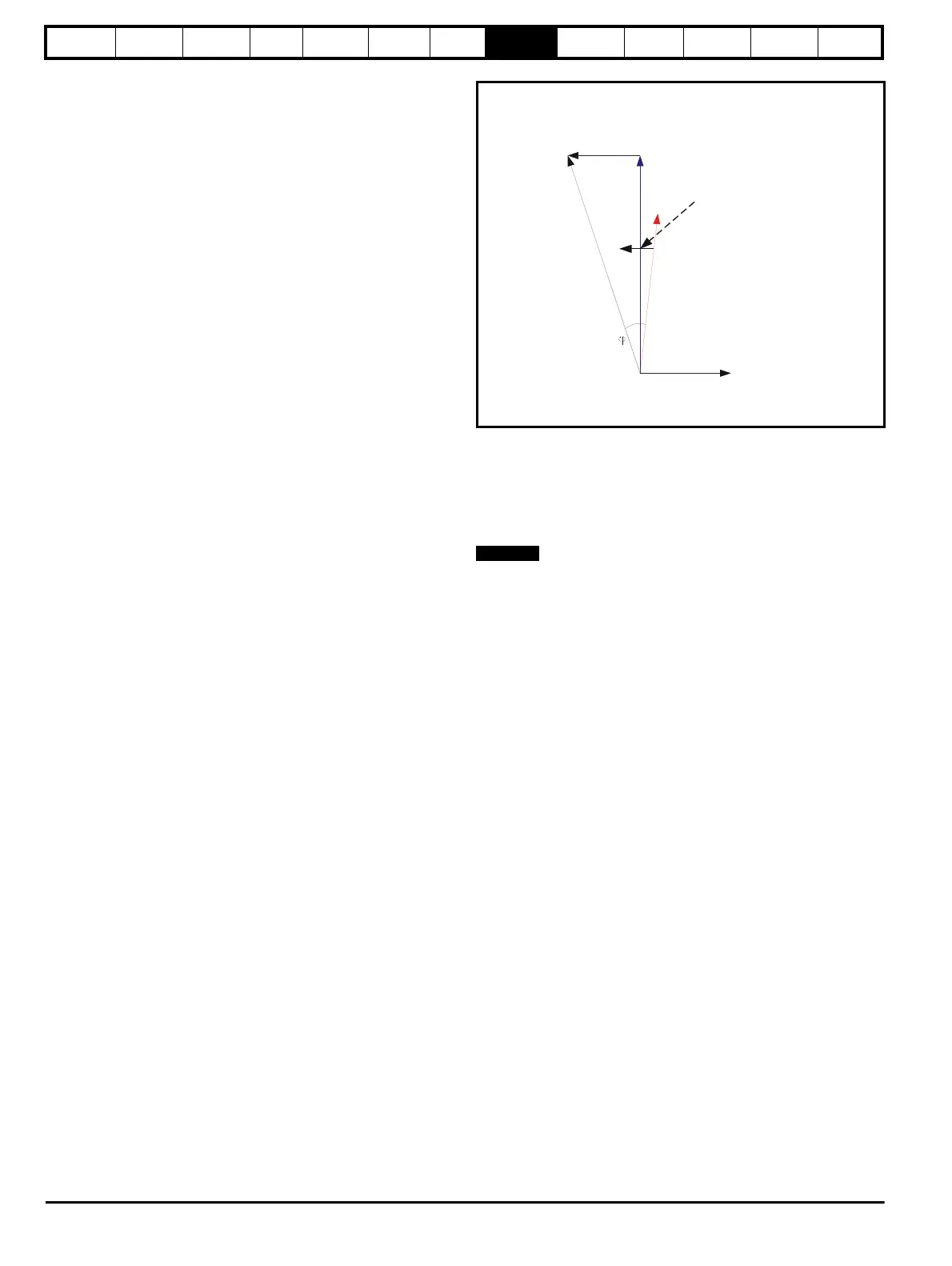
Figure 8-4 Power flow from supply to Regen drive
Vs Supply voltage
Vr Voltage at Regen drive terminals
Ir Total current at Regen drive terminals
JwLIr Voltage across Regen inductor
Power factor
The drive can control the reactive current / power, but not the real power.
8.6 Current trimming
A current feedback trimming routine runs before the Regen drive is
enabled to minimise offsets in the current feedback. If Current Trim
Mode (03.011) = 0 the current offset trim is only carried out once when
the drive comes out of the under voltage state and is not repeated unless
the supply is removed and re-applied. The current offset trim is only
carried out when the charge system is enabled (contactor open) as this
minimizes current flowing into the inverter terminals due to noise on the
supply that may disturb the current offset trimming.
Current Trim Mode (03.011) should be set to one if the current offset trim
is required each time when the Regen drive is enabled. To ensure that
the current offset trim is not disturbed by noise on the supply, the charge
system is enabled before the current offset trim and then disabled again
before the Regen drive goes into its active state. This causes the charge
system contactors to switch each time the Regen drive is enabled.
8.7 Voltage ramp time control (Pr 03.022)
When a Regen drive is enabled and has synchronized to the supply, the
DC bus voltage is at a level equal to the peak line to line voltage.
The voltage controller is then enabled and attempts to raise the DC bus
voltage to the set-point defined by Voltage Set Point (03.005).
The voltage reference is ramped up to the requried level at a rate
defined by Voltage Ramp Time (03.022) in V/ms. The default value of
1.0 V/ms ensures limited over-shoot when the DC bus voltage reaches
the required level. If a shorter synchronization time is required then the
ramp rate can be increased, however care must be taken to avoid over-
voltage trips particularly if a high level is used for the DC bus voltage set-
point. If a faster ramp rate and high set-point are required it may be
necessary the increase Voltage Controller Proportional Gain Kp (03.006)
to minimise over-shoot.
Voltage across
regen inductor
Isx
JwLIr
Vs
Vr
Ir
X axis componen
current
Power
factor
Modifying Ir directly
affects power factor

 Loading...


