Safety
information
Introduction
Product
Information
System
design
Mechanical
Installation
Electrical
Installation
Getting
started
Optimization Parameters
Technical
data
Component
sizing
Diagnostics
UL
Information
Unidrive M Regen Design Guide 153
Issue Number: 4
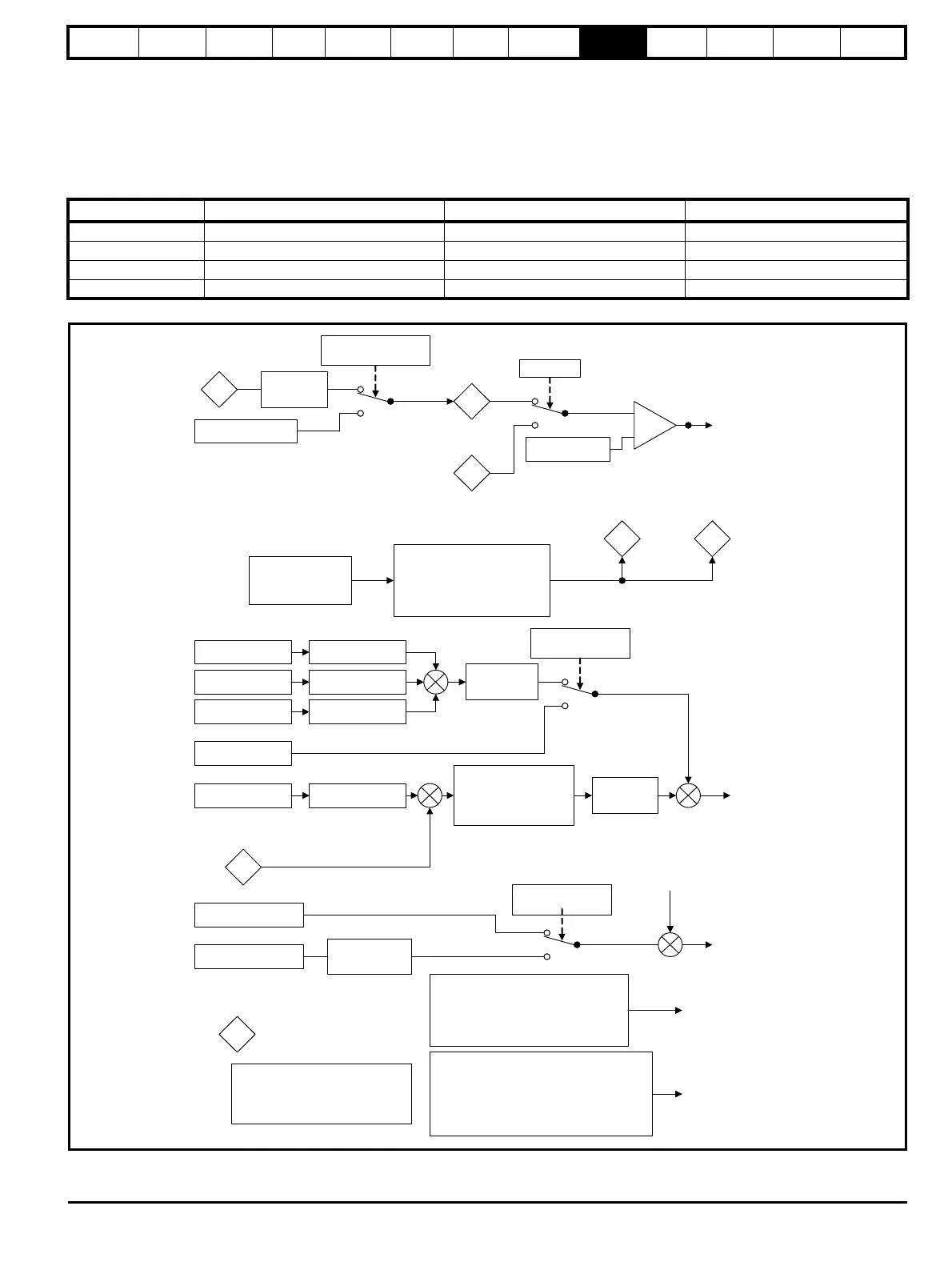
9.3 Menu 3: Regen Control
In Regen mode the drive assumes the mains is lost, it does not close the input, and does not attempt synchronization if the DC bus voltage is below
the levels given in the table below.
If the unit is synchronized and the DC bus voltage falls below this level the unit is disabled and the Regen drive main contactor is opened.
The Regen drive also monitors the voltage at it's AC terminals (U, V and W) for mains loss and if this falls below the levels given in the table, the unit
is disabled and the Regen drive main contactor is opened.
Figure 9-1 Menu 3 Regen logic diagram
Voltage rating DC voltage mains loss detection level AC voltage mains loss detection level DC voltage for supply healthy
200 V 205 Vdc 75 Vac 215 Vdc
400 V 410 Vdc 150 Vac 430 Vdc
575 V 540 Vdc 225 Vac 565 Vdc
690 V 540 Vdc 225 Vac 565 Vdc
Charge System
Disabled / Contactor
Closed (03.008)
Regen mode sequencer
Regen Synchronisation Mode (03.004)
Current Trim Mode(03.011)
Synchronisation Headroom
(03.035)
03.007
Disable Charge
System / Close
Contactor
03.009
Synchronised
Power Input 1 (03.010)
Power Input 2 (03.013)
Power Input 3 (03.014)
+
+
+
Power Input 1 Scaling
(03.015)
Power Input 2 Scaling
(03.016)
Power Input 3 Scaling
(03.017)
Power to current
conversion
Power Input kW
(03.018)
Power Input Mode
(03.012)
Voltage Set Point
(03.005)
Voltage Ramp Time
(03.022)
_
+
Voltage Controller
Proportional Gain Kp (03.006)
(No user access to Ki)
05.005
D.c. Link Voltage
+
+
Modulation
depth
compensation
Active current
reference to
menu 4
Reactive power
input kVAR (03.020)
Reactive current
reference (04.008)
Reactive power
input mode (03.019)
Reactive Power to
current conversion
Reactive current
reference to
menu 4
03.001
Reactive
Power
0
1
0
1
Voltage Detectors
Regen Minimum Voltage(03.026)
Regen Maximum Voltage(03.027)
Harmonic reduction mode (03.021)
Regen Minimum Frequency (03.024)
Regen Maximum Frequency (03.025)
+
+
Current injected for
island detection
0*
1
Supply Voltage Detection
Mode (03.029)
Supply Voltage(03.028)
05.005
D.c. Bus
voltage
Convert to
supply voltage
03.036
Estimated Supply
Voltage
0
1
05.002
Output
Voltage
Synchronised
+
-
Regen Supply Loss
a.c. Level (03.023)
Island Detector
Island Detection Enable(03.030)
Island Detection Injection Frequency (03.031)
Island Detection Level(03.032)
Island Detection Synchronisation SourceSelect (03.033)
Island Detection Synchronisation Source(03.034)
Voltage Range
trips
Island trip
*If Supply Voltage Detection Mode (03.029) = 0 then
Estimated Supply Voltage(03.036) is only updated
when the system is not enabled and whenD.c. Bus
Voltage 05.005 has become stopped rising or falling.
Also the synchronisation process will not begin on
enable until this point is reached.

 Loading...


