Safety
information
Introduction
Product
Information
System
design
Mechanical
Installation
Electrical
Installation
Getting
started
Optimization Parameters
Technical
data
Component
sizing
Diagnostics
UL
Information
24 Unidrive M Regen Design Guide
Issue Number: 4
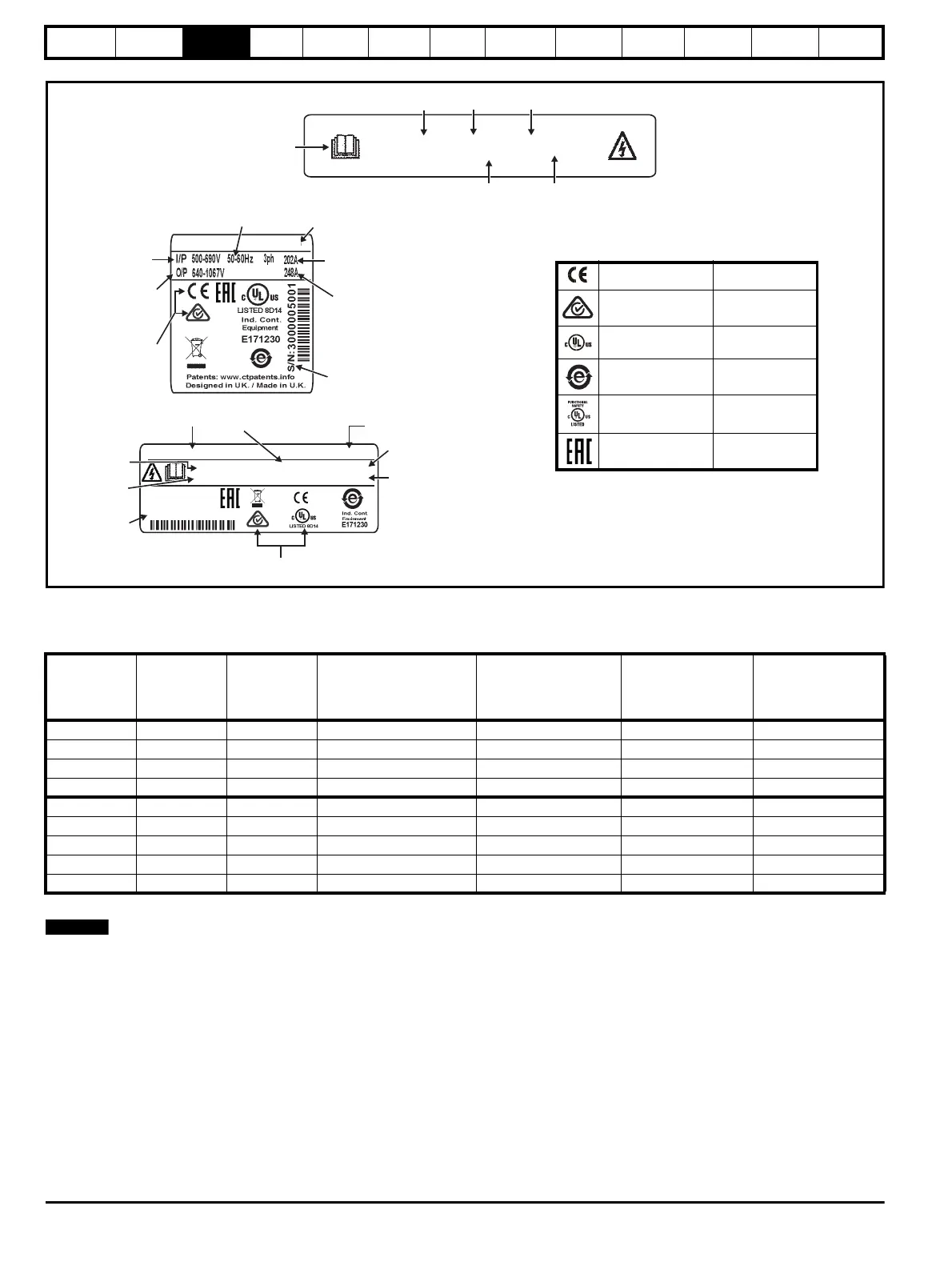
Figure 3-9 Typical rectifier rating labels
3.6 Unidrive M Rectifier technical data
Table 3-5 Rectifier ratings at 40 °C (104 °F)
* Twin rectifier
The fuse and cable data in Table 3-5 are based on continuous operation of the Unidrive M rectifier. When using a Unidrive M rectifier to soft start a
regen system the charging currents for the system should be calculated.
Model
Voltage
rating
Typical input
current
Maximum continuous
input current
Maximum overload
input current
Typical continuous
DC output current
Maximum DC
output current
VA A A
AA
10204100 200 333 361 494 409 413
10404520 400 370 396 523 452 455
10502430 575 202 218 313 243 246
10602480 690 202 225 313 247 251
11406840 400 557 594 752 684 689
11503840 575 313 338 473 384 387
11604060 690 331 362 465 406 411
1142X400* 400 2 x 326 2 x 358 2 x 397 2 x 395 2 x 400
1162X380* 690 2 x 308 2 x 339 2 x 375 2 x 375 2 x 380
Refer to
User Guide
Model
Frame
size
Voltage
Current rating
Rectifier format
RECT-106 02480 A
Approvals
Input voltage
Output
voltage
Date code
Serial
number
Input
frequency
No.of phases &
Typical input current for
Normal Duty rating
Output current
1717
RECT-106 02480 A STDN39
I/P 500-690V 50-60Hz 3ph 202A
O/P 640-1067V 247A
Designed in UK
Made in U.K.
Serial No: 3000005001
Input current
Output current
Model
Input
frequency
Date code
Approvals
Serial
number
Output
voltage
Input
voltage
1717
CE approval Europe
RCM regulatory
compliance mark
Australia
UL / cUL approval USA & Canada
RoHS compliant China
Functional safety USA & Canada
Eurasian conformity Eurasia

 Loading...


