Safety
information
Introduction
Product
Information
System
design
Mechanical
Installation
Electrical
Installation
Getting
started
Optimization Parameters
Technical
data
Component
sizing
Diagnostics
UL
Information
76 Unidrive M Regen Design Guide
Issue Number: 4
5 Mechanical Installation
This chapter describes the installation of the Regen drive components.
Key features of this chapter include:
• Regen component dimensions
• Enclosure sizing and layout
• Enclosure ventilation
• Enclosure design with high ambient temperatures
Refer to the Mechanical Installation sections in the relevant Unidrive M
Power Installation Guide for drive mechanical information.
5.1 Safety information
5.2 Planning the installation
The following considerations must be made when planning the
installation:
5.2.1 Access
Access must be restricted to authorised personnel only. Safety
regulations which apply at the place of use must be complied with.
The IP (Ingress Protection) rating of the drive is installation dependent.
For further information, please refer to the relevant Unidrive M Power
Installation Guide.
5.2.2 Environmental protection
The drive must be protected from:
• moisture, including dripping water or spraying water and
condensation. An anti-condensation heater may be required, which
must be switched off when the drive is running.
• contamination with electrically conductive material.
• contamination with any form of dust which may restrict the fan, or
impair airflow over various components.
• temperature beyond the specified operating and storage ranges.
During installation it is recommended that the vents on the drive are
covered to prevent debris (e.g. wire off-cuts) from entering the drive.
5.2.3 Cooling
The heat produced by the drive / additional components must be
removed without its specified operating temperature being exceeded.
Note that a sealed enclosure gives much reduced cooling compared with
a ventilated one, and may need to be larger and/or use internal air
circulating fans.
For further information, please refer to section 5.5.2 Enclosure sizing on
page 102.
Through hole mounting is possible for all Unidrive M modules and the
Unidrive M Rectifier which can reduce cubicle heating and cooling
requirements. Refer to relevant Unidrive M Power Installation Guide or
Unidrive M Modular Installation Guide.
5.2.4 Electrical safety
The installation must be safe under normal and fault conditions.
Electrical installation instructions are given in Chapter 6 Electrical
Installation on page 105.
5.2.5 Fire protection
The drive enclosure is not classified as a fire enclosure. A separate fire
enclosure must be provided.
For installation in the USA, a NEMA 12 enclosure is suitable.
For installation outside the USA, the following (based on IEC 62109-1,
standard for PV inverters) is recommended.
Enclosure can be metal and/or polymeric, polymer must meet
requirements which can be summarized for larger enclosures as using
materials meeting at least UL 94 class 5VB at the point of minimum
thickness.
Air filter assemblies to be at least class V-2.
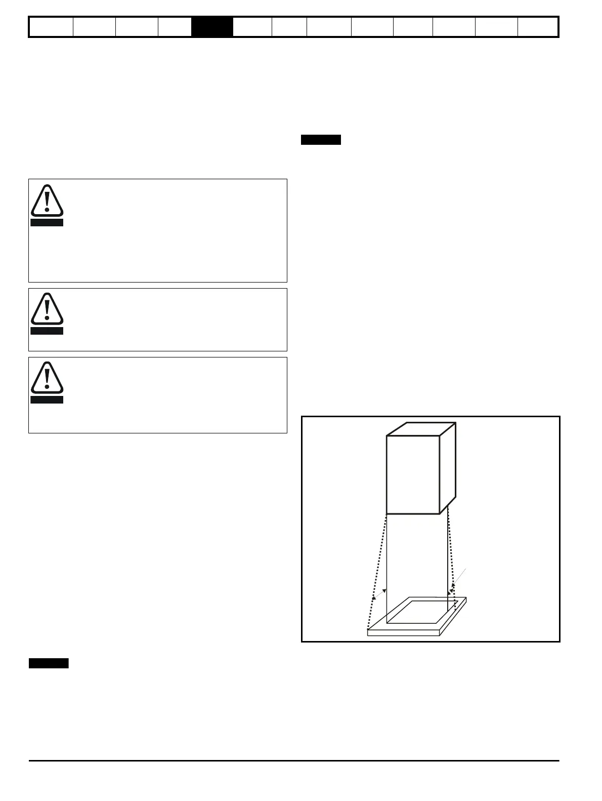
The location and size of the bottom shall cover the area shown in
Figure 5-1. Any part of the side which is within the area traced out by the
5° angle is also considered to be part of the bottom of the fire enclosure.
Figure 5-1 Fire enclosure bottom layout
The bottom, including the part of the side considered to be part of the
bottom, must be designed to prevent escape of burning material - either
by having no openings or by having a baffle construction.
This means that openings for cables etc. must be sealed with materials
meeting the 5VB requirement, or else have a baffle above.
See Figure 5-2 for acceptable baffle construction. This does not apply
for mounting in an enclosed electrical operating area (restricted access)
with concrete floor.
Follow the instructions
The mechanical and electrical installation instructions must
be adhered to. Any questions or doubt should be referred to
the supplier of the equipment. It is the responsibility of the
owner or user to ensure that the installation of the drive and
any external option unit, and the way in which they are
operated and maintained, comply with the requirements of
the Health and Safety at Work Act in the United Kingdom or
applicable legislation and regulations and codes of practice in
the country in which the equipment is used.
Competence of the installer
The drive must be installed by professional assemblers who
are familiar with the requirements for safety and EMC. The
assembler is responsible for ensuring that the end product or
system complies with all the relevant laws in the country
where it is to be used.
Enclosure
The drive is intended to be mounted in an enclosure which
prevents access except by trained and authorized personnel,
and which prevents the ingress of contamination. It is
designed for use in an environment classified as pollution
degree 2 in accordance with IEC 60664-1. This means that
only dry, non-conducting contamination is acceptable.

 Loading...


