Safety
information
Introduction
Product
Information
System
design
Mechanical
Installation
Electrical
Installation
Getting
started
Optimization Parameters
Technical
data
Component
sizing
Diagnostics
UL
Information
Unidrive M Regen Design Guide 77
Issue Number: 4
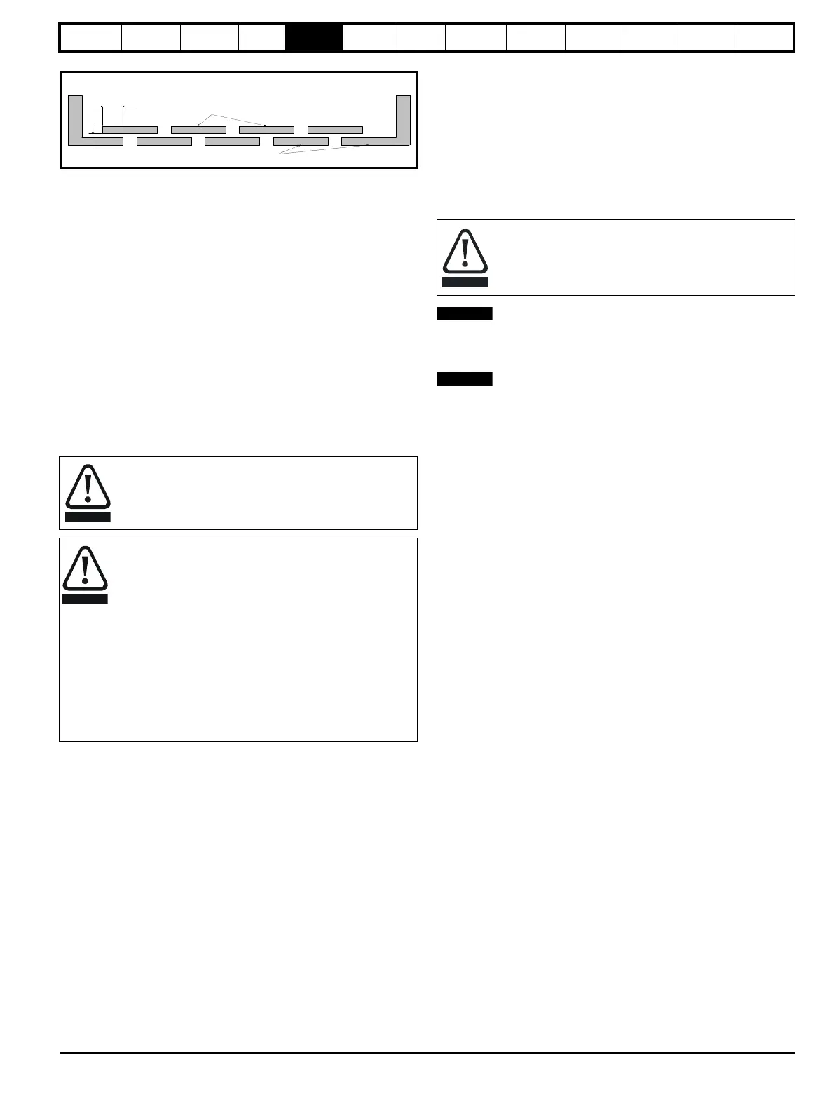
Figure 5-2 Fire enclosure baffle construction
5.2.6 Electromagnetic compatibility
Variable speed drives are powerful electronic circuits which can cause
electromagnetic interference if not installed correctly with careful
attention to the layout of the wiring.
Some simple routine precautions can prevent disturbance to typical
industrial control equipment.
If it is necessary to meet strict emission limits, or if it is known that
electromagnetically sensitive equipment is located nearby, then full
precautions must be observed. Refer to the guidelines given in the
relevant Unidrive M Power Installation Guide. The DC bus voltage in a
Regen system with a 400 V supply is usually 700 V, which corresponds
to an AC supply voltage of 519 V. Unless the motor cable is less than
10 m long it is recommended that either an inverter-grade motor is used
or else output chokes should be installed to protect the motor from the
effect of the fast-rising output voltage pulses.
5.2.7 Hazardous areas
The drive must not be located in a classified hazardous area unless it is
installed in an approved enclosure and the installation is certified.
5.3 Regen component dimensions
The dimensions listed are for the following items:
• Regen inductor
• Switching frequency filter inductor
• Switching frequency filter capacitor
•Varistors
• External EMC filter
• Combined regen input filters
5.3.1 Regen inductor
When installing the following Regen inductors into the system, ensure no
enclosures are fitted directly around the inductors thereby preventing air
flow and natural cooling.
All Regen inductors can be mounted in the base of the enclosure as
shown in Figure 5-6, with relevant details in Table 5-1, Table 5-2 and
Ta ble 5- 3.
Regen inductors which are only suitable for base mounting i.e. not back
panel mounting as shown in Figure 5-7, are highlighted with an
*
Table 5-1, Table 5-2 and Table 5-3.
Isolation device
The AC supply must be disconnected from the drive using an
approved isolation device before any cover is removed from
the drive or before any servicing work is performed.
Stored charge
The drive contains capacitors that remain charged to a
potentially lethal voltage after the AC supply has been
disconnected. If the drive has been energized, the AC
supply must be isolated at least ten minutes before work
may continue.
Normally, the capacitors are discharged by an internal
resistor. Under certain, unusual fault conditions, it is possible
that the capacitors may fail to discharge, or be prevented
from being discharged by a voltage applied to the output
terminals. If the drive has failed in a manner that causes the
display to go blank immediately, it is possible the capacitors
will not be discharged. In this case, consult the supplier of the
drive or their authorised distributor.
Not less
th a n 2 X
B affle p la te s (m a y b e
above or below bottom
of enclosure)
X
B o tto m of fire
enclosure
Not less
than 2
times ‘X’
Baffle plates (may be above or
below bottom of enclosure)
Bottom of fire enclosure
X
The following Regen inductors can produce significant losses
with a normal operating temperature in the region of 150 °C
dependant upon the ambient temperature. Location of the
Regen inductor should be considered to avoid damage to
heat sensitive components or create a fire risk.

 Loading...


