Safety
information
Introduction
Product
Information
System
design
Mechanical
Installation
Electrical
Installation
Getting
started
Optimization Parameters
Technical
data
Component
sizing
Diagnostics
UL
Information
Unidrive M Regen Design Guide 41
Issue Number: 4
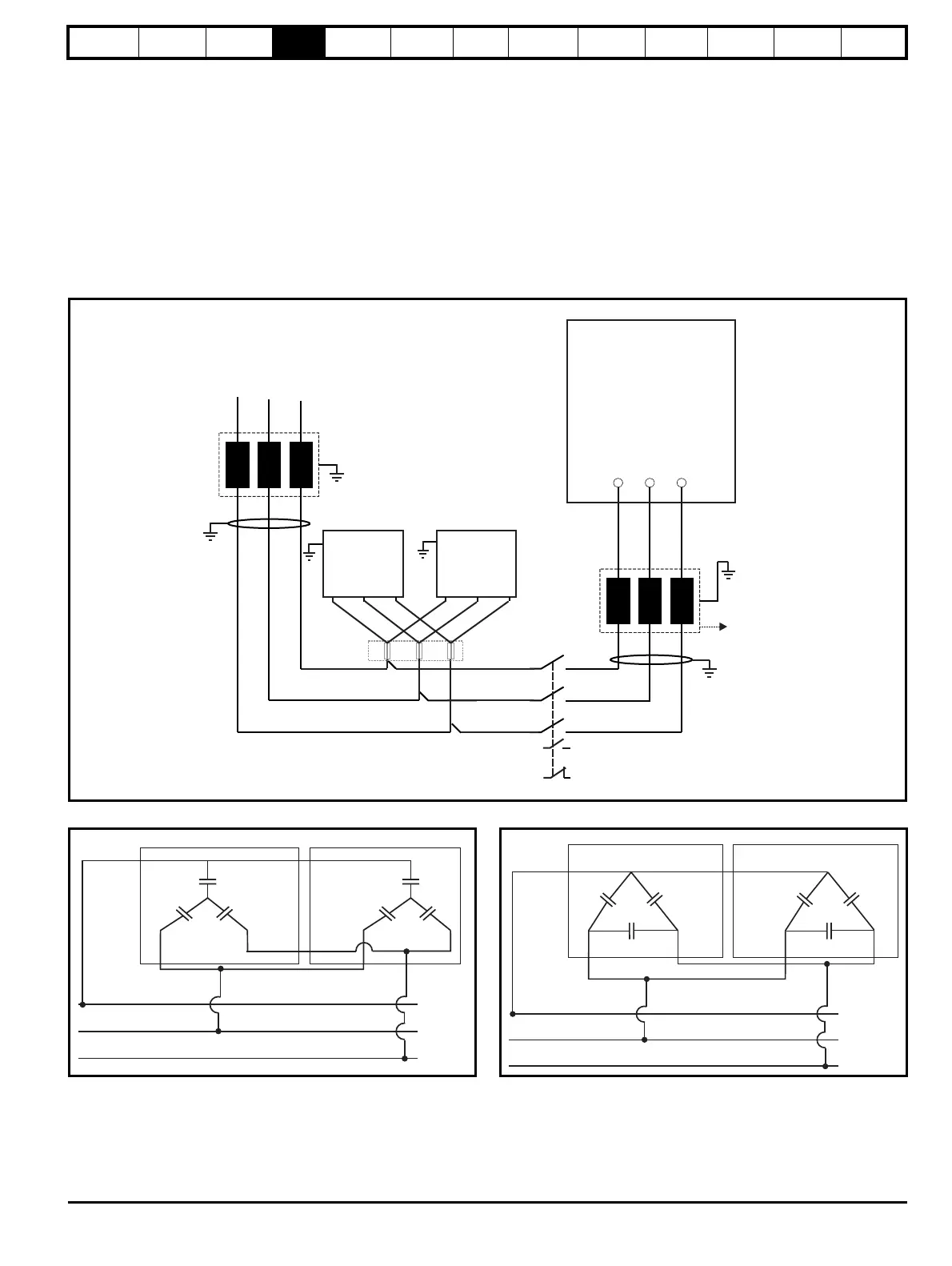
4.3 Switching frequency filter capacitor wiring configuration to support 8 % THD
v
(Total Harmonic Distortion Voltage)
The wiring configuration of SFF capacitors is dependent on the regen drive size. For all drive sizes there is either one or two banks of capacitors,
Cap bank A and Cap bank B. For certain drive sizes only Cap bank A is used and for other drive sizes Cap bank A and Cap bank B are used.
Cap bank A and Cap bank B can be wired in either a Star or Delta configuration, depending on the drive size. Refer to Table 3-14 to Table 3-17 for
further information.
There are 4 configurations of capacitor wiring:
• Cap bank A wired in Star, Cap bank B not fitted
• Cap bank A wired in Delta, Cap bank B not fitted
• Cap bank A and Cap bank B both wired in Star
• Cap bank A and Cap bank B both wired in Delta
Figure 4-1 Example of SFF capacitor bank
Figure 4-2 Star configuration Figure 4-3 Delta configuration
UVW
L2
AC Supply
Connections
Unidrive M
Regen drive
K2
Aux.2a
Aux.2b
L1
Cap bank A
Cap bank B
F7 F8 F9
U
V
W
C4
C5
C6
C1
C2
C3
Cap bank A
Cap bank B
C6
C1
C2
C3
U
V
W
C4
C5
Cap bank A
Cap bank B

 Loading...


