Safety
information
Introduction
Product
Information
System
design
Mechanical
Installation
Electrical
Installation
Getting
started
Optimization Parameters
Technical
data
Component
sizing
Diagnostics
UL
Information
54 Unidrive M Regen Design Guide
Issue Number: 4
4.4 Switching frequency filter capacitor wiring configuration to support 2 % THD
v
4.4.1 Single Regen, single motoring system to support up to 2 % THD
v
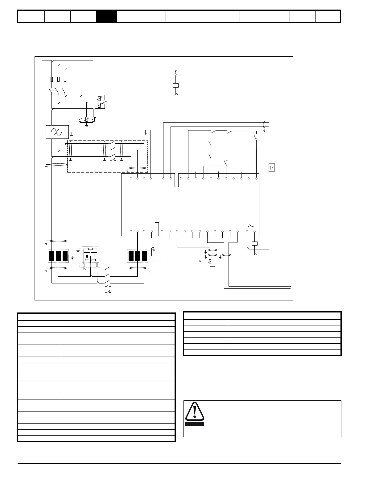
Figure 4-9 Power connections: Single Regen, single motoring system
* Unidrive M Frame 11 and all new generation Inductors only.
Figure 4-9 shows both the power and control connections for the standard Regen
solution this being a single Regen and single motoring drive system.
For this solution the Vac supply is temporarily connected to the Regen drive’s L1,
L2, L3 inputs for initial power-up only, removing the need for an external charging
circuit. The main AC supply to L1, L2, L3 on the Regen drive (K3) is interlocked
with the Regen drive’s enable preventing operation when the charging circuit is still
connected.
UVW
-DC +DC
L1
L2
L3
-DC
+DC
21
1
2 3 4 5 6 7 8 9 10 11 41 42
22 23 24 25 26 27 28 29 30 31
T.30
T.24
L1
L2
EMC
K1
F1 F2 F3
VDR1
VDR2
VDR3
VDR4
VDR6
Tc.1
AC Supply
Power-up
Connections
AC Supply
Connections
Motoring
drive DC
Connections
+24 output
Enable motor drive
Contactor closed
0common
Drive enable
K2
Rly.1
(optional)
L1 L2 L3 PE
Aux.3
Unidrive M
Regen drive
S1
Aux.2a
Regen inductor
thermistor
0V common
V
V
Drive OK
Reset input
Aux.3
S6
Contactor
control
VDR5
Vsupply
K3
Charging branch circuit
K3
Vsupply
Aux.2b
Supply
ground
Power feed
forward I/P
0V common
Note: Surge suppressors to be fitted to contactor coils.
C1
K2
Aux.2a
Aux.2b
F7 F8 F9F7 F8 F9
Table 4-6 Key to Figure 4-9
Key Description
L1, L2, L3 Three phase supply
F1, F2, F3 Main Regen system supply fuses
VDR1, VDR2, VDR3 Varistor network line-to-line
VDR4, VDR5, VDR6 Varistor network line-to-ground
EMC Optional EMC Filter
C1 Switching frequency filter capacitor
L1 Switching frequency filter inductor
L2 Regen inductor
K1 Main supply switch or contactor
K2 Regen drive main contactor
K3 Charging contactor
Aux.3 K3 NC auxiliary contact
Aux.2a K2 NO auxiliary contact
Aux.2b K2 NC auxiliary contact
Rly.1
Optional isolation for enable between Regen and motoring drive
Mt.1 Motor thermistor
Tc.1 Regen inductor thermistor
Vsupply System control supply
+DC, -DC Motoring drive power connection to Regen drive
F7, F8, F9 Optional switching frequency filter capacitor fuses
S1 Regen drive enable
S2 Motoring drive enable
S3 Motoring drive reset
S4 Motoring drive run forward
S5 Motoring drive run reverse
S6 Regen drive reset input (Pr 08.024 = Pr 10.033)
Regen inductor thermistor must be configured to disable the drive
in the event of a thermal overload. The switching frequency filter
inductor thermistor must be configured to open the main supply
contactor in the event of a thermal overload. This can be
achieved through the use of an external thermal protection
device/relay.
Table 4-6 Key to Figure 4-9
Key Description

 Loading...


