Safety
information
Introduction
Product
Information
System
design
Mechanical
Installation
Electrical
Installation
Getting
started
Optimization Parameters
Technical
data
Component
sizing
Diagnostics
UL
Information
Unidrive M Regen Design Guide 11
Issue Number: 4
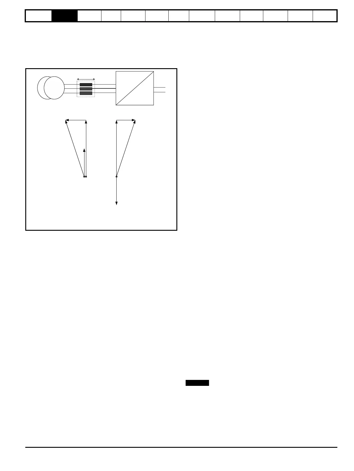
2.4 Power flow
The following phasor diagram illustrates the relationship between the
supply voltage and the Regen drive voltage. The angle between the two
voltage vectors is approximately 5° at full load, this can result in a near
unity power factor of 0.996, depending on the grid supply conditions.
Figure 2-1
The direction of the power flow can be changed relative to the supply
voltage, by making small changes to the Regen drives output voltage
and phase.
2.5 Synchronization
The synchronization of the Regen drive to the supply does not require
additional hardware. The space vector modulator within the Regen drive
represents the angle and magnitude of the AC supply at all times. This
however is not the case when the AC supply is first connected or when
the Regen drive is disabled.
Unless some form of synchronization is carried out the current
controllers will start with values of zero resulting in zero volts being
applied to the inverter output terminals. The phase locked loop (PLL)
would also start with zero and so would not lock onto the supply.
To overcome these problems the following information must be obtained
before the Regen drive attempts to start:
1. The mains supply voltage vector magnitude
2. The angle of the supply voltage vector
3. The frequency of the supply
These values are obtained by carrying out a synchronization on enable
• The first stage of the pre-start tests is to measure the initial DC bus
voltage, which by default, is assumed to be equal to the peak line-to-
line voltage of the supply.
• The second stage of the pre-start test is to apply two short pulses of
zero volts at the converter input. These pulses must be short enough
so that the peak current is less than the over current trip level of the
converter. The time between the pulses must also be long enough
so that the current built up in the input inductors during the first pulse
has decayed to a low level before the second pulse is applied.
These are used to calculate the instantaneous angle of the supply
voltage vector during the first test pulse. The second test pulse is
then applied at time Td later to allow the supply frequency to be
calculated.
At this stage the supply inductance is also calculated.
• Once the synchronization is complete the phase locked loop (PLL) is
set-up. At this point the whole control system could be started and
should operate without any large transients.
• To improve the robustness of the start-up phase a further short test
pulse voltage vector, with the same magnitude and phase as the
estimated supply voltage vector is applied. This is to detect
measurement errors that could have occurred because of supply
distortion present during the pre-start tests. The Regen drive may
not synchronize to the supply if the grid voltage is highly distorted.
2.6 Current trimming
A current feedback trimming routine runs before the drive is enabled to
minimise offsets in the current feedback. This feature can be user
configured, for more details refer to section 8.6 Current trimming on
page 144.
2.7 Regen system configurations
The Regen drive has been designed to provide a regulated DC supply to
other motoring drives. The Regen drive gives bi-directional power flow
with sinusoidal currents and a near unity power factor.
Following are the possible configurations for Unidrive M Regen:
• Single Regen, single motoring (Figure 4-4 on page 42).
• Single Regen, multiple motoring using a Unidrive M Rectifier
(Figure 4-5 on page 44).
• Single Regen, multiple motoring using an external softstart resistor
(Figure 4-6 on page 46).
• Multiple Regen, multiple motoring using a Unidrive M Rectifier
(Figure 4-7 on page 48).
• Regen drive as brake resistor replacement (Figure 4-8 on page 52).
Refer to section 3.3 Ratings on page 17, for the Regen drive ratings.
The sizing of a Regen system must take into account the following
factors:
• Line voltage
• Motor rated current, rated voltage and power factor
• Maximum load power and overload conditions
In general, when designing a Regen system, equal Regen and motoring
drive rated currents will work correctly. However, care must be taken to
ensure that under worst case supply conditions the Regen drive is able
to supply or absorb all the required power. In multi-drive configurations,
the Regen drive must be of a sufficient size to supply the net peak power
demanded by the combined load of all the motoring drives and total
system losses.
If the Regen drive is unable to supply the full power required by the
motoring drive, the DC bus voltage will drop and in severe cases may
lose synchronization with the mains and trip. If the Regen drive is unable
to regenerate the full power from the motoring drive on the DC bus, then
the Regen and motoring drive(s) will trip on over-voltage.
2.8 Regen drive system types
2.8.1 Single Regen, single motoring system
Figure 2-2 shows a typical layout for a standard Regen system
consisting of a single Regen drive and single motoring drive. In this
configuration the Regen drive is supplying the motoring drive and
passing the regenerative energy back to the mains supply.
The power up connections to L1, L2, L3 of the Regen drive are only
made during power-up. Once both drives are powered up, this is
switched out and the main Regen supply switched in. The auxiliary on
the charging circuit to the Regen drive’s L1, L2, L3 connections for
power up must be closed (charging supply removed) before the Regen
drive can be enabled.
r
V
r
V
r
r
V
s
I
I
Power flow
from supply
Power flow
back to supply
V Supply voltage
s
V Voltage at line terminals of Regen drive
r
j LI Voltage across Regen inductor
r
I Current at line terminals of Regen drive
r
AC
DC
U
V
W
+DC
-DC
I
r
V
s
VAC
Supply
V
r
JLI
r
jLI
r
jLI
r
V
s

 Loading...


