Safety
information
Introduction
Product
Information
System
design
Mechanical
Installation
Electrical
Installation
Getting
started
Optimization Parameters
Technical
data
Component
sizing
Diagnostics
UL
Information
12 Unidrive M Regen Design Guide
Issue Number: 4
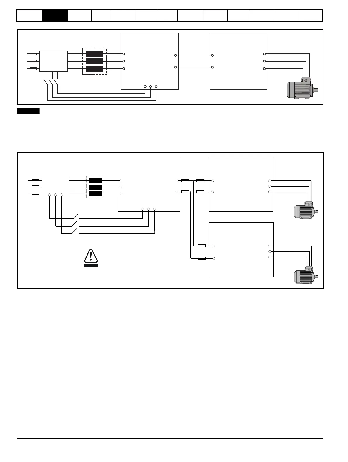
Figure 2-2 Single Regen, single motoring system
For the above single Regen, single motoring configuration; the Regen drive must be of the same frame size or larger.
2.8.2 Single Regen, multiple motoring system
Figure 2-3 and Figure 2-4 show the layout for a Regen system consisting of a single Regen drive with multiple motoring drives. In this configuration
the Regen drive is sized to the total power of all motoring drives.
Figure 2-3 Single Regen, multiple motoring system using an external softstart resistor
It is also possible to have a single Regen drive powering multiple motoring drives as shown with the power up connections also being provided via the
Regen drives L1, L2, L3 inputs and using the Regen drives own internal softstart.
Unidrive M
Regen drive
L1
L2
L3
Additional
circuitry
Regen
inductor
U
V
W
AC supply
connection
+DC
-DC
DC bus
connections
Unidrive M
Motoring drive
+DC
-DC
U
W
V
L1
L2
L3
Power up only
Motor
Connection
U
V
W
AC Supply
Connection
Unidrive M
Regen Drive
DC Bus
Connections
L1
L2
L3
Regen
Inductor
Additional
Circuitry
-DC
+DC
U
V
W
-DC
+DC
Motor
Connection
Unidrive M
Motoring Drive
U
V
W
Motor
Connection
Unidrive M
Motoring Drive
-DC
+DC
L1
L2 L3
Power up only
CAUTION
The internal EMC filter must be removed
from all drives in the regen system
(motoring and regen).

 Loading...


