Safety
information
Introduction
Product
Information
System
design
Mechanical
Installation
Electrical
Installation
Getting
started
Optimization Parameters
Technical
data
Component
sizing
Diagnostics
UL
Information
Unidrive M Regen Design Guide 13
Issue Number: 4
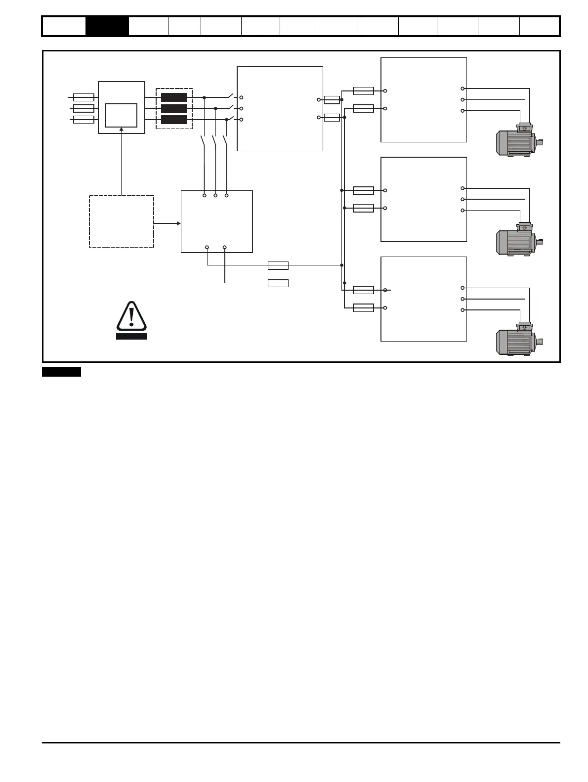
Figure 2-4 Single Regen, multiple motoring system using a Unidrive M rectifier
For a single Regen and multiple motoring drive arrangement optional charging circuits can be used for the increased inrush current generated by the
additional capacitance of the multiple motoring drives. The charging circuit can consist of either a Unidrive M rectifier module or an external softstart
resistor as detailed in Chapter 4 System design on page 40.
Unidrive M
Regen drive
L1
L2
L3
Additional
circuitry
Regen
inductor
U
V
W
AC supply
connection
+DC
-DC
Unidrive M
Motoring drive 2
+DC
-DC
U
W
V
Unidrive M
Motoring drive 3
+DC
-DC
U
W
V
Unidrive M
Motoring drive 1
+DC
-DC
U
W
V
External
charging
circuit
Unidrive M
Rectifier
Charging circuit can
consist of either
Unidrive M rectifier
or external
charging circuit as
detailed in Chapter 4
System Design
+DC -DC
L1 L2 L3
DC Bus
connections
Motor
connection
Motor
connection
Motor
connection
CAUTION
The internal EMC filter must be removed
from all drives in the regen system
(motoring and regen).

 Loading...