Safety
information
Introduction
Product
Information
System
design
Mechanical
Installation
Electrical
Installation
Getting
started
Optimization
Parameters
Technical
data
Component
sizing
Diagnostics
UL
Information
Unidrive M Regen Design Guide 143
Issue Number: 1
8.2 Regen controllers
The Regen drive uses a DC bus voltage controller with inner current
controllers as shown in Figure 8-2:
Figure 8-2 Regen controllers
The gains of the voltage and current controllers affect the stability of the
Regen system, with incorrect settings resulting in over-voltage or over-
current trips.
8.3 Current loop gains
The defaults current loop gains (Kp, Pr 04.013 and Ki, Pr 04.014) are
suitable for most standard Regen systems. However if the input
inductance is significantly higher the proportional gain may need to be
adjusted as described following.
The most critical parameter for stability is the current controller
proportional gain, Pr 04.013. The required value for this is dependent
upon the Regen drives input inductance. If the inductance of the supply
is a significant proportion of the recommended Regen inductor
i.e. 60/I
DR
mH per phase,
Where:
I
DR
is the drive rated current
then the proportional gain may need to be increased.
The supply inductance is likely to be negligible compared to the Regen
inductor value with small drives, but is likely to be significant with larger
drives. The proportional gain, Pr 04.013 should be adjusted as
described following using the total inductance per phase.
The proportional gain, Pr 04.013 can be set by the user so that
Pr 04.013 = Kp = (L / T) x (I
fs
/ V
fs
) x (256 / 5)
Where:
T is the sample time of the current controllers. The drive compensates
for any change of sample time, and so it should be assumed that the
sample time is equivalent to the lowest sample rate of 167 s.
L is the total input inductance.
I
fs
is the peak full-scale current feedback
I
fs
= Full Scale Current Kc (11.061) x 2
Vfs is the maximum DC bus voltage.
Therefore:
Pr
04.013
= Kp = (L / 167 s) x (Kc x 2 / Vfs) x (256 / 5)
= K x L x Kc
Where:
K = [2 / (Vfs x 167 s)] x (256 / 5)
There is one value of the scaling factor K for each drive voltage rating as
shown in the table below.
This set-up will give a step response with minimum overshoot after a
step change of current reference. The approximate performance of the
current controllers will be as given below. The proportional gain can be
increased by a factor of 1.5 giving a similar increase in bandwidth,
however, this gives a step response with approximately 12.5 %
overshoot.
Table 8-1 Current loop sample times
As previously detailed the current controller integral gain, Pr 04.014 is
not so critical with the recommended value being the default setting.
8.4 Voltage controller proportional gain
Kp (Pr 03.006)
The DC bus voltage is controlled by a PI controller, which provides the
reference for the real component of current from the inverter terminals to
the supply. The power input parameters (Power Input 1 (03.010),
Power Input 2 (03.013), Power Input 3 (03.014) or Power Input kW
(03.018)) are provided to give a power feed forward term, at the output
of the PI controller, from the motor drives connected to the DC bus.
If possible the power feed forwards should be used so that the PI
controller is simply providing a trim to the DC bus voltage. In most cases
the default voltage controller gains can be used, however the effect of
the gains and the response of the voltage controller is discussed below.
For the purpose of analyzing the voltage controller response it is
assumed that a power feed-forward term is not provided. If the power
flow from the DC bus is increased (i.e. motor is accelerated by a motor
drive connected to the DC bus) the DC bus voltage will fall, but the
minimum level will be limited to just below the peak rectified level of the
supply provided the maximum rating of the unit is not exceeded. If the
power flow to the DC bus is increased (i.e. motor is decelerated by a
motor drive connected to the DC bus) the DC bus voltage will rise. If the
peak of the DC bus voltage reaches the over voltage level the Regen
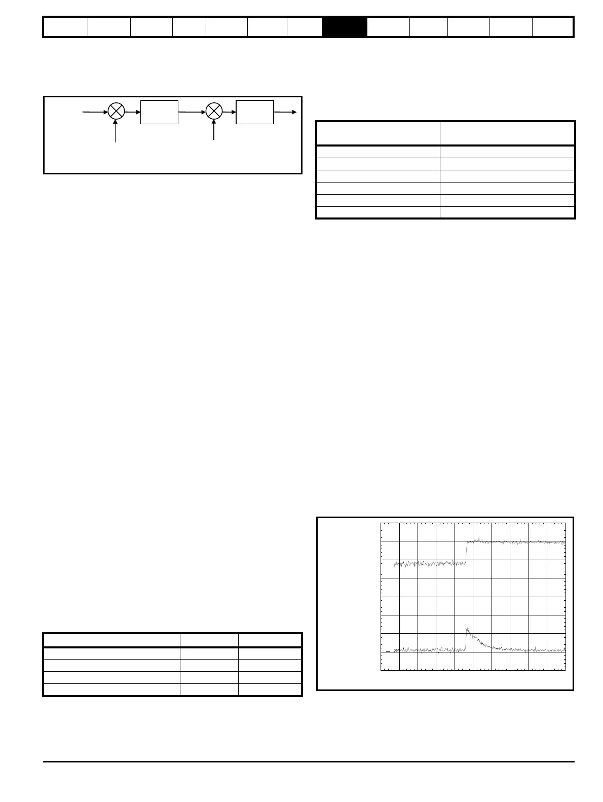
drive will trip. A rapid transient where power into the DC bus is increased
is shown below in Figure 8-3.
Figure 8-3 DC Bus transient
The example shown is for a very rapid load change where the torque
reference of the motor drive has been changed instantly from one value
to another.
Drive voltage rating (11.033) Vfs K
200 V 415 V 1045
400 V 830 V 522
575 V 990 V 438
690 V 1190 V 364
Voltage
controller
Current
controllers
-
-
DC bus
voltage
feedback
Current
feedback
Pr DC03.005
bus voltage
set point
Switching frequency kHz
Current control sample time (T)
s
3 167
4 125
683
8 62.5
12 83
16 62.5
Regen unit
DC bus voltage
Real current
100ms/div

 Loading...


