Safety
information
Introduction
Product
Information
System
design
Mechanical
Installation
Electrical
Installation
Getting
started
Optimization Parameters
Technical
data
Component
sizing
Diagnostics
UL
Information
Unidrive M Regen Design Guide 45
Issue Number: 4
Ensure that cables from both capacitor banks to the fuses, where fitted, are of a similar length.
Where varistors other than those listed in Table 3-22 are fitted branch circuit protection may be required, where this is the case, follow the manufacturers
recommendations.
DC bus fusing is required for all motoring drives in a single Regen, multiple drive system in both the +DC and -DC.
VDR1, VDR2 and VDR3 when operating with a 690 Vac supply should consist of two varistors each in series as detailed in Table 3-22 on page 38.
To prevent inductive voltage spikes surge suppressors should be fitted to the contactor coils.
The Regen inductor
core losses are directly dependant on the switching frequency and specific core material
and therefore selection is critical. As a result
only Regen inductors specified in this guide should be used.
SFF branch circuit protection may be required, refer to section 3.9.3 Switching frequency filter capacitor on page 30.
If K2 is installed in the position shown in Figure 4-5 then discharge resistors should be installed to the SFF Cap Bank A and where installed, Cap Bank B.
If K2 is installed on the supply side of Cap Bank A and Cap Bank B then a discharge resistor is not required. Refer to Table 10-35 Discharge resistor
details for SFF capacitors to support 8 % THDv on page 300.
See Chapter 10 Technical data on page 276 for fuse rating information.
Unidrive M Rectifier
For a Regen system, the rectifier can be used to charge the common DC bus when the power is first applied, however this will once the Regen system is
powered up no longer be required.
The total amount of capacitance on the common DC bus that the rectifier can drive is limited due to the inrush current (produced during power up and
during brownouts). See Table 3-9 on page 26 for the capacitance limit. Unidrive M drive DC bus capacitance levels are available in Table 11-1 on
page 308.
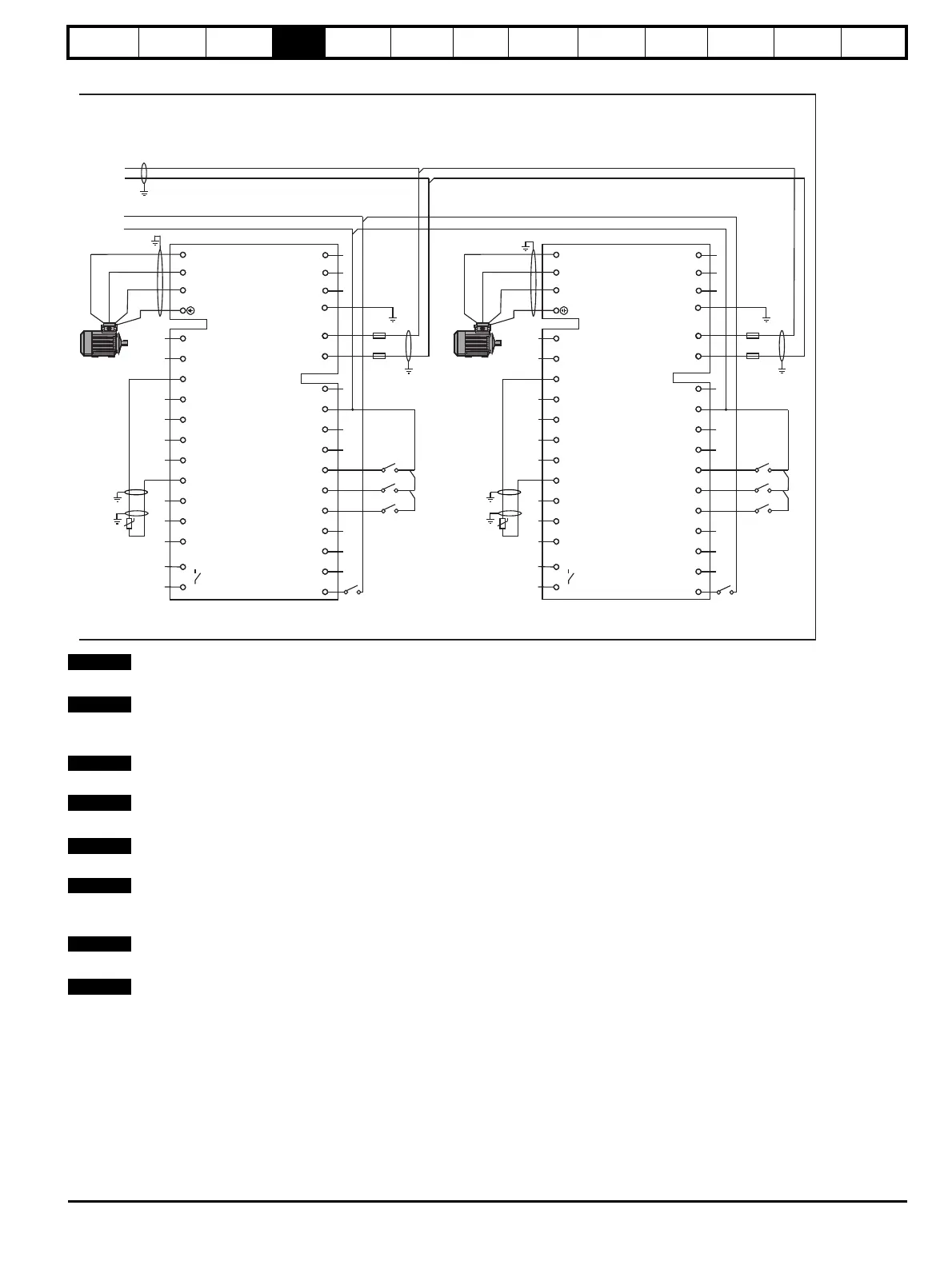
-DC
+DC
F7
F8
UVW
L1 L2 L3 PE
-DC +DC
21
1
2 3 4 5 6 7 8 9 10 11 41 42
22 23 24 25 26 27 28 29 30 31
T.30
T.24
S5
Mt.1
AC Supply
Connections
NOT USED
Connections
Motoring
drive DC
Connections
U
V
W
PE
S2
S3 S4
Drive enable
0V common
Drive reset
Run forward
Run reverse
Motor thermistor
0V common
F9
F10
UVW
L1 L2 L3 PE
-DC +DC
21
1
2 3 4 5 6 7 8 9 10 11 41 42
22 23 24 25 26 27 28 29 30 31
S5
Mt.2
AC Supply
Connections
NOT USED
Connections
Motoring
drive DC
Connections
U
V
W
PE
S2
S3 S4
Drive enable
0V common
Drive reset
Run forward
Run reverse
Motor thermistor
0V common
+24V output
+24V output
Motor
Motor
Drive OK
Drive OK
Unidrive M
Motoring drive
Unidrive M
Motoring drive

 Loading...